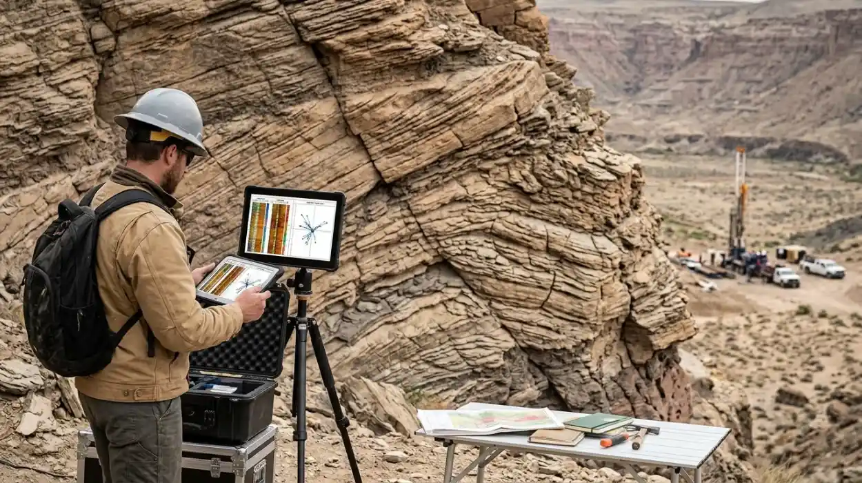
Dipmeter and image log analysis is the high-resolution geological interpretation of borehole electrical and acoustic measurements to determine subsurface bedding orientation, structural dip, fault geometry, and sedimentary depositional environments, enabling energy organisations to reduce drilling uncertainty and optimise hydrocarbon reservoir development.
Subsurface exploration teams rely on borehole imaging tools to capture micro-resistivity and acoustic reflectance data along the wellbore wall. Standard wireline logs, such as gamma-ray and neutron-density logs, measure bulk rock properties at a vertical resolution of 0.3 to 0.6 metres. Borehole image logs achieve a vertical resolution of 2.5 to 5 millimetres, exposing thin laminations, fracture apertures, and sedimentary cross-bedding that conventional logging tools miss entirely.
In corporate energy environments, geoscience departments use dipmeter log analysis to construct accurate three-dimensional structural models. Formation dip measurement quantifies the angle and azimuth of geological beds relative to true north and horizontal planes. When geoscientists integrate bedding orientation data with seismic surveys, reservoir engineering teams calculate gross rock volume and hydrocarbon-in-place figures with greater precision.
Sedimentary analysis utilises borehole images to identify palaeocurrent directions, depositional facies, and reservoir compartmentalisation. Reservoir engineers and geologists distinguish between structural dip, which reflects post-depositional tectonic tilting, and stratigraphic dip, which represents primary depositional features such as channel bars or aeolian dunes. Accurate differentiation prevents asset teams from misinterpreting reservoir continuity and drilling dry development wells.
How does corporate training in dipmeter and image log interpretation work?
Corporate training in dipmeter and image log interpretation operates through structured, multi-stage technical upskilling programs that combine foundational petrophysical theory, interactive software workshops, and real-world well-log case studies to build measurable geological evaluation capabilities across subsurface asset teams.
Organisations implement technical geoscience training by first conducting a structured skills gap audit across exploration, development, and drilling departments. Learning and Development (L&D) managers evaluate current interpreter proficiency in identifying borehole breakouts, induced fractures, and sedimentary structures. Establishing a baseline competence score allows training leads to group participants by technical seniority, such as junior geologists, operations geologists, and senior reservoir engineers.
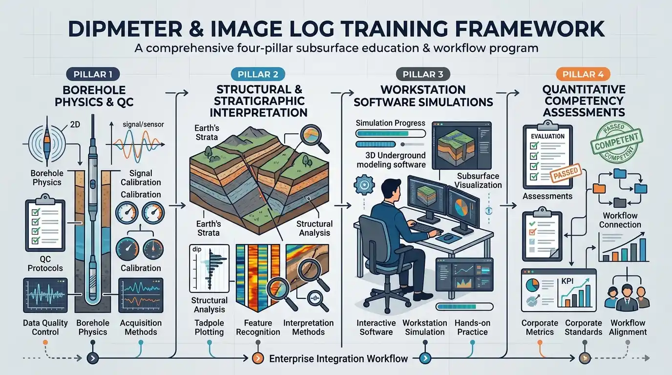
The curriculum progresses through four sequential phases over a standard 5-day intensive workshop or a 4-week modular hybrid schedule. Phase one covers tool physics, contrasting micro-resistivity pads used in conductive water-based muds against ultrasonic acoustic televiewers deployed in oil-based mud environments. Phase two trains participants in quality control protocols, including speed correction, button normalisation, and pad-to-pad correlation checks.
Phase three transitions learners into workstation-based dip interpretation techniques using industry-standard petrophysical software platforms. Participants manually pick sine waves on unwrapped borehole images, calculate tadpole plots, and generate stereonets and rose diagrams. Phase four integrates structural dip analysis with stratigraphic correlation across multi-well field datasets, requiring teams to defend their geological models in peer-reviewed technical presentations.
To bridge the gap between theoretical awareness and practical execution, technical teams often transition from foundational concepts to specialized workflows such as how to apply dipmeter and image log data to evaluate formation dip and geological structures. Structured competence assessments conclude the training cycle, measuring interpretation accuracy against benchmark field datasets before learners return to active drilling projects.
What are the key components of a dipmeter and image log training framework?
A comprehensive dipmeter and image log training framework comprises four core pillars: borehole physics and quality control protocols, structural and stratigraphic interpretation methodologies, workstation software simulations, and quantitative competency assessments aligned with corporate subsurface workflows.
Technical Curriculum Modules
A rigorous technical syllabus covers the physical principles of Formation MicroImager (FMI), Ultrasonic Borehole Imager (UBI), and high-resolution dipmeter tools. Learners study how borehole wall rugosity, mudcake thickness, and tool eccentralisation distort raw electrical curves. The curriculum establishes strict mathematical procedures for removing structural tilt from raw dip measurements to restore original sedimentary palaeocurrent directions.
Core Analytical Methodologies
Training programs embed standardized geological interpretation workflows to ensure consistency across global asset teams. Key methodologies include:
Tadpole Plot Classification: Categorising dip patterns into green (constant structural dip), red (upward-increasing dip indicating faults or drag folds), and blue (upward-decreasing dip signifying current bedding or unconformities) motifs.
Geomechanical Stress Analysis: Identifying drilling-induced tensile fractures and borehole breakouts to determine maximum and minimum horizontal stress orientations.
Facies and Fracture Characterisation: Distinguishing open, conductive natural fractures from healed, resistive mineralised fractures to predict reservoir permeability anisotropy.
Delivery Formats and Experiential Tools
Corporate L&D teams deploy blended learning architectures to minimise operational downtime for active field personnel. Delivery formats include instructor-led classroom workshops, virtual live-streamed workstation labs, and self-paced digital simulation modules. Case-based learning utilises blind field datasets from basins such as the North Sea, Permian Basin, and Middle Eastern carbonate platforms, requiring participants to solve authentic structural puzzles under realistic operational deadlines.
Performance Metrics and Evaluation Frameworks
Organisations measure training effectiveness using Kirkpatrick’s four-level evaluation model adapted for technical geoscience disciplines. Quantitative metrics include pre- and post-training technical test scores, time-to-competency benchmarks for new hires, and reductions in well-log interpretation turnaround times. Programs such as a structured Dipmeter and Image Log Applications Training Course incorporate capstone projects where interpreters must deliver a complete structural and sedimentary audit of a multi-well field.
What measurable benefits does structured borehole image training deliver to organisations?
Structured borehole image training delivers measurable organisational returns by reducing non-productive drilling time by 15% to 25%, accelerating subsurface model turnaround by 30%, increasing reservoir recovery factors, and strengthening internal technical talent retention.
Energy companies face substantial financial exposure when subsurface teams misinterpret complex fault blocks or fractured reservoirs. A single misplaced offshore appraisal well costs between $15 million and $50 million. Equipping internal asset teams with rigorous dip interpretation techniques reduces reliance on external third-party consultants, saving organizations $150,000 to $400,000 annually per asset team in outsourced service fees.
Operational efficiency improves when geologists, petrophysicists, and drilling engineers share a common technical vocabulary. Cross-disciplinary training eliminates communication bottlenecks during real-time geosteering operations. When operations geologists accurately identify bedding orientation changes while drilling horizontal wells, drilling teams adjust wellbore trajectories immediately, keeping the drill bit within the high-permeability pay zone for over 85% of the lateral section.
Workforce stability and leadership pipeline development represent critical long-term advantages for HR managers and technical directors. Technical professionals remain with employers that invest in advanced, career-advancing workstation competencies. Organisations that implement structured geoscience upskilling report a 12% to 18% improvement in mid-career specialist retention and build a resilient internal succession pipeline for chief geologist and subsurface manager roles.
Which corporate teams and industries use dipmeter and image log competencies?
Dipmeter and image log competencies are deployed across exploration and production (E&P) operators, oilfield service companies, carbon capture and storage (CCS) developers, and geothermal energy firms by multidisciplinary teams including structural geologists, petrophysicists, reservoir engineers, and drilling specialists.
Upstream Oil and Gas Exploration and Development
In conventional and unconventional hydrocarbon operations, exploration teams use structural dip analysis to validate seismic horizons across sub-seismic fault zones. Reservoir engineering departments integrate fracture aperture and orientation data from borehole images into dual-porosity dynamic simulation models. This integration enables accurate prediction of water breakthrough pathways and optimises hydraulic fracturing stage placement in tight shale formations.
Carbon Capture, Utilisation, and Storage (CCUS)
CCUS project developers rely heavily on borehole image log interpretation to certify caprock integrity and storage reservoir containment. Subsurface teams analyse high-resolution acoustic and resistivity images to verify that regional sealing formations are free of conductive fracture networks that could allow injected carbon dioxide to migrate upward. Regulatory bodies require documented evidence of structural and geomechanical stability before granting injection permits.
Geothermal Energy and Mining Sectors
Deep geothermal developers utilise image logs to map natural permeable fracture zones in crystalline basement rocks, which serve as the primary fluid conduits for heat extraction. Mining and geotechnical engineering firms deploy optical and acoustic televiewers to evaluate rock mass stability, joint orientations, and slope failure risks in open-pit and underground excavation projects.
Corporate Functional Roles
Within these sectors, specific corporate departments apply borehole imaging data to distinct operational deliverables:
Operations Geology Teams: Execute real-time stratigraphic correlation and geosteering adjustments during active drilling campaigns.
Petrophysics Departments: Calibrate permeability transforms and distinguish matrix porosity from fracture porosity in heterogeneous carbonate reservoirs.
Drilling and Geomechanics Engineers: Design stable mud weight windows by mapping borehole breakout widths and stress directions.
What common problems and misconceptions undermine technical geoscience training?
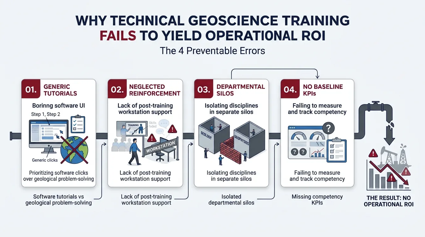
Technical geoscience training frequently fails to produce operational ROI due to four preventable errors: relying on generic vendor software tutorials instead of geological problem-solving, neglecting post-training workstation reinforcement, isolating disciplines in departmental silos, and failing to establish baseline competency KPIs.
Misconception 1: Automated Software Picking Replaces Geological Expertise
Many corporate decision-makers assume modern petrophysical software algorithms automatically extract accurate dip data from raw image logs. Automated dip-picking routines frequently misidentify drilling-induced fractures, borehole breakouts, and mudcake artifacts as true geological bedding planes. Without trained interpreters who understand structural geology principles, automated workflows generate corrupted tadpole plots that distort reservoir models.
Misconception 2: One-Off Lectures Create Lasting Operational Competence
Organisations often invest in theoretical lecture series without providing hands-on workstation exercises using authentic, imperfect field data. When learners return to their desks, retention of complex interpretation rules drops by 70% within 30 days due to the forgetting curve. Effective corporate training requires active simulation labs, immediate mentor feedback, and structured post-course project milestones.
Misconception 3: Image Log Training is Exclusively for Petrophysicists
Restricting borehole image training to petrophysical specialists creates institutional bottlenecks. Petrophysicists excel at tool physics and curve processing, while structural geologists and sedimentologists possess the domain expertise required to interpret tectonic regimes and depositional systems. High-performing energy organisations train integrated asset teams together, ensuring geologists, petrophysicists, and reservoir engineers collaborate seamlessly on subsurface interpretation.
Misconception 4: Training ROI Cannot Be Quantified in Subsurface Teams
L&D leaders occasionally treat technical training as a compliance expense rather than a measurable capital investment. When organisations fail to define pre-training baselines—such as average interpretation hours per well or frequency of geosteering sidetracks—they cannot calculate post-training financial returns. Establishing clear operational KPIs before training begins enables executives to track exact reductions in consulting spend, faster field development approvals, and improved drilling accuracy.
Frequently Asked Questions
What is oil and gas borehole imaging used for in subsurface exploration?
Oil & Gas Borehole Imaging generates high-resolution electrical and acoustic images of the wellbore wall to identify structural dip, natural fractures, and sedimentary bedding features. Through specialised programmes at the Institute For Oil & Gas Training, geoscientists learn to integrate these measurements with seismic and core data to reduce geological uncertainty and optimise reservoir placement.
How does borehole imaging differ from conventional wireline logging?
Conventional wireline logs measure bulk rock properties such as porosity and gamma radiation at a vertical resolution of roughly 0.3 to 0.6 metres, whereas Oil & Gas Borehole Imaging captures detailed features down to 2.5 millimetres. This micro-scale resolution allows subsurface teams to detect thin laminations, fault planes, and fracture apertures that standard logging tools miss.
Who needs training in oil and gas borehole imaging interpretation?
Geologists, petrophysicists, reservoir engineers, and drilling specialists responsible for field development, geosteering, and geomechanical modelling require practical borehole imaging competencies. The Institute For Oil & Gas Training structures its curriculum for multidisciplinary asset teams to ensure consistent structural and stratigraphic interpretation across exploration and production workflows.
Which types of logging tools are used in borehole image acquisition?
Oil & Gas Borehole Imaging relies primarily on micro-resistivity imaging tools for conductive water-based drilling muds and ultrasonic acoustic televiewers for non-conductive oil-based mud environments. Selecting the appropriate tool depends on borehole fluid properties, rock lithology, and whether the primary evaluation objective is fracture characterisation or sedimentary facies analysis.
How does borehole image analysis improve drilling and reservoir performance?
Accurate Oil & Gas Borehole Imaging enables asset teams to map regional stress orientations, prevent wellbore instability, and steer horizontal wells precisely within productive pay zones. Organisations that develop internal interpretation capabilities through the Institute For Oil & Gas Training reduce non-productive drilling time and improve overall hydrocarbon recovery factors.
Related training courses
Borehole Image Applications in Sedimentology Training Course
- Specialisation
- Oil & Gas Borehole Imaging
- Duration
- 5 days · 15 CPD hours
Borehole Image Analysis for In-Situ Stress Evaluation Training Course
- Specialisation
- Oil & Gas Borehole Imaging
- Duration
- 5 days · 15 CPD hours
Borehole Image Interpretation for Bedding and Dip Analysis Training Course
- Specialisation
- Oil & Gas Borehole Imaging
- Duration
- 5 days · 15 CPD hours
More articles
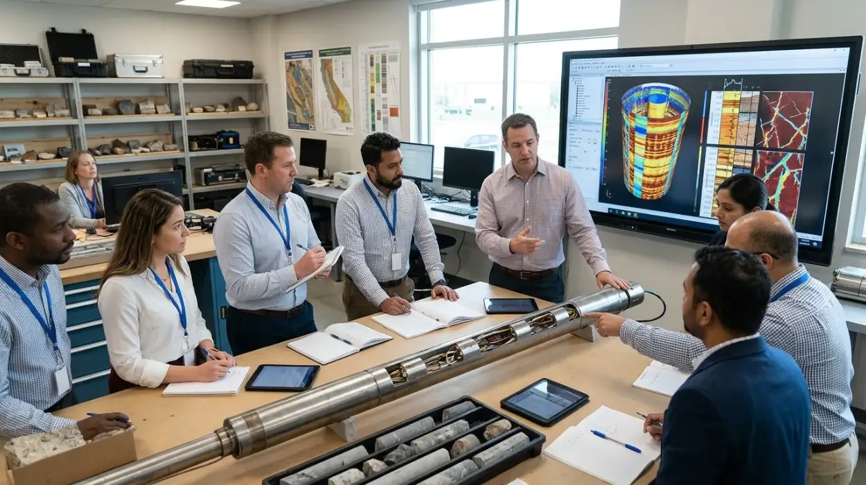
Electrical Borehole Imaging Technologies Training by Institute For Oil & Gas Training
Discover the curriculum, learning outcomes, and enrollment process for the Electrical Borehole Imaging Technologies Training Course.
Read article →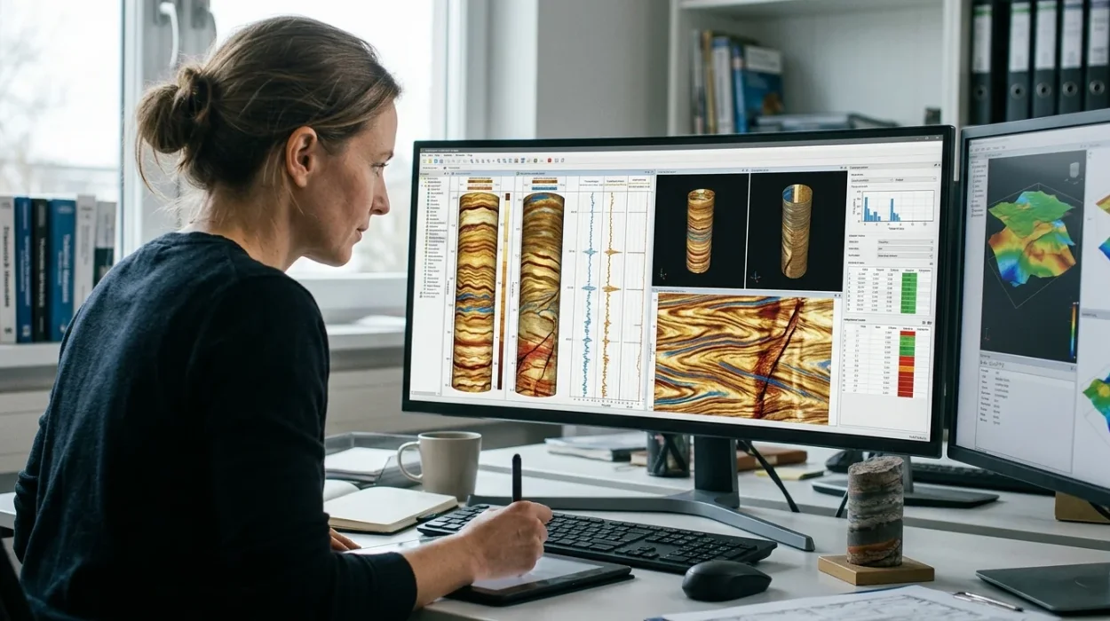
How to Evaluate Electrical Borehole Imaging Technologies and Their Applications in Formation Analysis
Master how to evaluate electrical borehole imaging technologies formation microimagers and resistivity logging tools for advanced subsurface analysis.
Read article →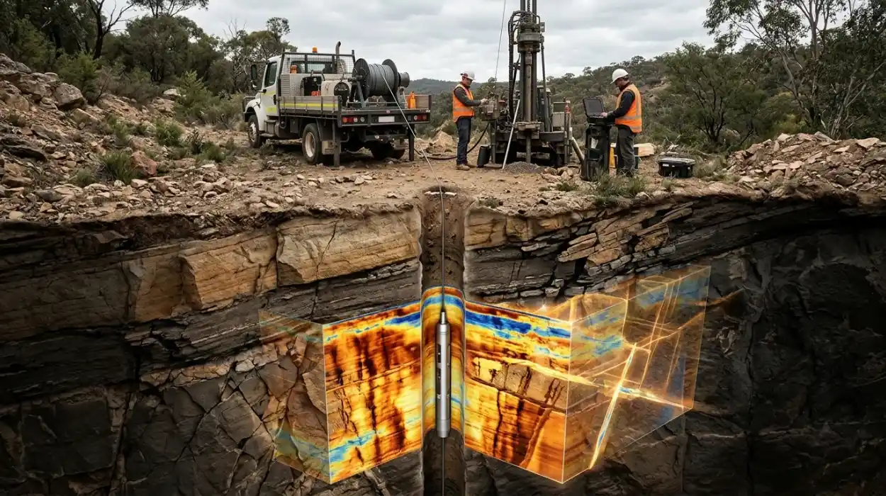
How Electrical Borehole Imaging Improves Subsurface Geological Understanding
Learn how electrical borehole imaging improves subsurface geological understanding and workforce competency through structured corporate technical training.
Read article →