Subsurface uncertainty costs exploration and production companies millions of dollars in misplaced wells, bypassed pay zones, and inefficient reservoir drainage. Technical teams require advanced petrophysical interpretation skills to convert raw wellbore data into actionable geological models. Corporate training programmes bridge the competency gap between conventional wireline logging and high-resolution borehole image analysis.
What Is Electrical Borehole Imaging and Why Do Technical Teams Need It?
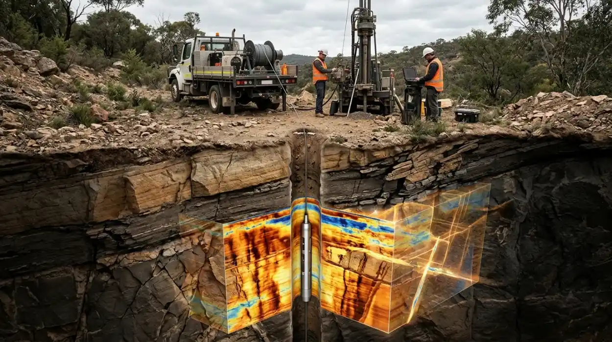
Electrical borehole imaging is a high-resolution wireline logging method that records micro-resistivity variations along the borehole wall to generate detailed structural and stratigraphic maps, enabling geoscience and engineering teams to reduce subsurface uncertainty and optimise drilling placement across complex reservoirs.
Conventional open-hole logging tools measure bulk formation properties at vertical resolutions ranging from 0.3 metres to 1.5 metres. These coarse measurements miss thin-bedded reservoirs, natural fracture networks, and subtle sedimentary structures that control fluid flow. Electrical imaging tools deploy articulated pads equipped with dozens of micro-electrodes pressed directly against the borehole wall. These electrodes inject electrical current into the formation and measure minute variations in resistivity at vertical and azimuthal resolutions down to 5 millimetres.
For energy organisations, the business impact of mastering resistivity image logging is substantial. Subsurface teams equipped with advanced interpretation capabilities identify thin pay intervals that conventional logs overlook, increasing recoverable reserve estimates by 12% to 18% in laminated clastic sequences. Geoscience managers rely on accurate dip and azimuth calculations from image logs to refine structural cross-sections and avoid costly sidetracks. When technical staff lack structured training in borehole image acquisition and processing, companies suffer from misidentified facies, inaccurate fracture aperture calculations, and suboptimal well completion designs.
How Does Corporate Training in Electrical Borehole Imaging Work in Practice?
Corporate training in electrical borehole imaging follows a structured four-stage competency framework combining theoretical petrophysics, software workstation simulations, real-field log calibration exercises, and quantitative assessments to transfer practical interpretation skills directly to multidisciplinary subsurface teams within 10 to 15 days.
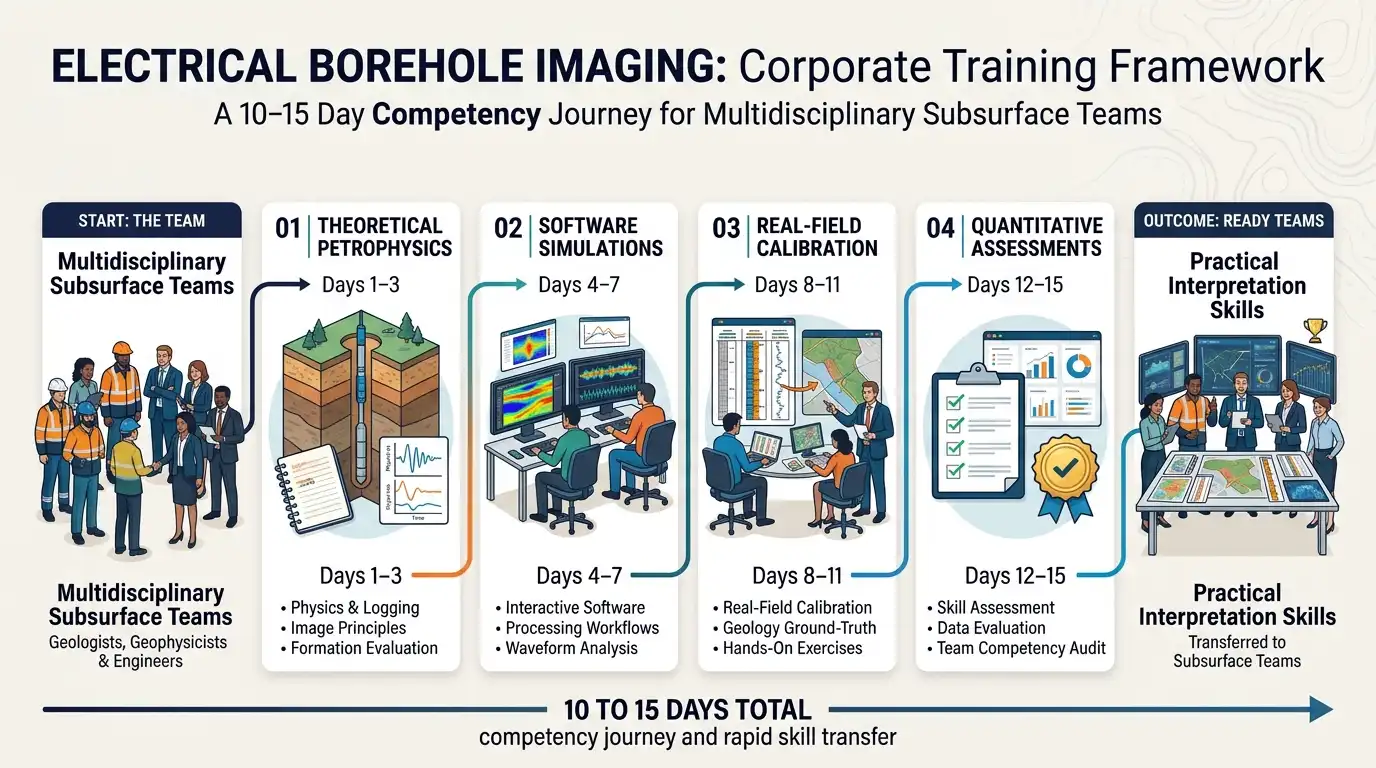
Organisations implement technical workforce development through a systematic instructional workflow designed to minimise operational downtime while maximising skill retention.
Stage 1: Technical Skill Gap Audit
Learning and development managers conduct pre-training diagnostic evaluations across geoscience departments, including petrophysics, structural geology, and reservoir engineering. These assessments measure baseline proficiency in electrical logging measurements, mud filtrate invasion mechanics, and dipmeter fundamentals. Diagnostic testing identifies specific knowledge deficits, such as distinguishing drilling-induced tensile fractures from natural open fractures in oil-based mud environments.
Stage 2: Modular Curriculum Delivery
Training providers deliver technical modules through blended learning formats tailored to corporate schedules. Live instructor-led workshops run for 4 hours daily over two weeks, supplemented by self-paced digital modules covering tool physics and quality control parameters. This hybrid structure allows asset teams in operational hubs, such as Aberdeen, Houston, and Abu Dhabi, to participate without halting active drilling support.
Stage 3: Workstation Simulation and Case-Based Calibration
Participants apply theoretical concepts using industry-standard petrophysical software suites and historical well datasets. Learners process raw inclinometer data, apply speed corrections, and perform static and dynamic image normalisation on actual field logs. Instructors guide teams through blind-test exercises where participants interpret unlabelled formation microimager datasets and compare their structural models against whole-core photographs.
Stage 4: Competency Validation and Workplace Transfer
At the conclusion of the programme, learners complete a capstone project involving a full-field multi-well correlation study. Technical leads evaluate participants against a standardised rubric measuring dip-picking accuracy, facies classification consistency, and report clarity. Organisations track post-training application over 90 days by auditing peer-reviewed well completion reports and measuring reductions in external consulting expenditure.
What Are the Key Components of an Electrical Borehole Imaging Curriculum?
An effective electrical borehole imaging curriculum integrates four core components: tool physics and acquisition mechanics, data processing and quality control workflows, structural and sedimentological interpretation frameworks, and multidisciplinary reservoir integration protocols supported by hands-on workstation labs.
Decision-makers evaluating technical curricula must ensure every module addresses real-world operational workflows rather than purely academic theory.
Tool Physics and Borehole Image Acquisition
This foundational module explains how pad-based micro-resistivity devices operate in conductive water-based muds versus resistive oil-based muds. Trainees examine button electrode arrays, pad coverage percentages across varying borehole diameters, and depth-of-investigation limits. Understanding hardware specifications prevents teams from misinterpreting tool artefacts, such as pad liftoff, stick-and-pull distortion, and dead buttons, as genuine geological features.
Image Processing and Quality Control Protocols
Raw telemetry from electrical imaging tools requires rigorous processing before geological analysis begins. Training covers accelerometer and magnetometer calibration, borehole drift correction, and pad-to-pad resistivity equalisation. Learners master the distinction between static normalisation, which preserves absolute resistivity contrasts across entire intervals, and dynamic normalisation, which enhances local textural features within sliding 0.6-metre windows.
Structural and Stratigraphic Interpretation Frameworks
Participants learn systematic classification schemes for picking bedding planes, faults, unconformities, and fracture networks. Modules cover tadpole plot analysis, stereonet projection techniques, and paleocurrent direction reconstruction from cross-bedded sandstones. When teams begin comparing hardware capabilities and planning field deployments, learning How to Evaluate Electrical Borehole Imaging Technologies and Their Applications in Formation Analysis provides the technical criteria required to match specific tool architectures to reservoir lithologies.
Multidisciplinary Integration and Delivery Formats
Technical training incorporates cross-functional workshops where petrophysicists collaborate with geomechanics specialists and drilling engineers. Delivery formats combine interactive virtual classrooms, physical core-workshop comparisons, and structured peer-review clinics. Enrolling teams in a dedicated Electrical Borehole Imaging Technologies Training Course ensures all subsurface disciplines share a unified geological vocabulary and standardised interpretation methodology.
What Measurable Business Outcomes Does Borehole Imaging Training Produce?
Structured electrical borehole imaging training reduces external petrophysical consulting costs by 35% to 50%, improves net-to-gross pay calculation accuracy by 15%, shortens well log turnaround times from 14 days to 48 hours, and increases technical staff retention rates by 22%.
Executive leaders and HR directors require quantifiable return on investment from technical learning initiatives. Upskilling internal geoscience teams delivers direct financial and operational gains across the exploration and production lifecycle.
Accelerated Interpretation Turnaround: In-house teams trained in rapid quality control and automated dip-picking workflows complete post-logging formation evaluations within 48 hours of wireline tool retrieval. Faster turnaround eliminates rig standby charges, which frequently exceed $85,000 per day on offshore installations.
Reduction in External Consulting Spend: Organisations that rely on third-party service companies for routine image log processing incur recurring fees averaging $15,000 to $25,000 per well. Internalising these workflows through targeted workforce training retains institutional knowledge and cuts annual vendor expenditure by up to 50%.
Improved Completion and Perforation Efficiency: Accurate identification of open versus mineralised natural fractures enables reservoir engineers to place hydraulic fracture stages and perforation clusters in productive zones. Operators report a 14% to 20% increase in initial well production rates following image-guided completion optimisation.
Enhanced Technical Talent Retention: Senior geoscientists and petrophysicists value structured career progression and access to advanced technical competencies. Companies investing at least 40 hours per year in specialised subsurface training achieve a 22% higher five-year retention rate among mid-career technical specialists.
Which Corporate Teams and Industries Benefit Most from This Training?
Electrical borehole imaging training directly benefits exploration geoscientists, development petrophysicists, reservoir engineers, geomechanics specialists, and drilling teams operating across upstream oil and gas, geothermal energy, carbon capture and storage, and deep mineral exploration sectors.
While conventional upstream hydrocarbon operators represent the primary adopters of FMI technology and resistivity image logging, energy transition industries increasingly depend on the exact same subsurface characterisation competencies.
Upstream Oil and Gas Asset Teams
Exploration and development teams in conventional and unconventional basins use borehole images to map fluvial channels, turbidite lobes, and carbonate vuggy porosity. Structural geologists rely on image-derived dip data to refine fault-block models and plan horizontal well trajectories that remain inside thin target reservoirs.
Geothermal Energy Developers
Enhanced geothermal systems depend entirely on fluid circulation through natural and stimulated fracture networks in crystalline basement rocks. Subsurface engineers in geothermal organisations use electrical borehole imaging to determine present-day maximum horizontal stress orientations from borehole breakouts and drilling-induced fractures, ensuring wellbores intersect permeable fracture pathways.
Carbon Capture and Storage (CCS) Operators
Regulatory frameworks for permanent geological carbon sequestration demand rigorous caprock integrity verification. CCS monitoring teams analyse high-resolution electrical images across seal formations to confirm the absence of transmissive faults or open fracture corridors that compromise containment security.
Mining and Geotechnical Engineering Firms
Deep-mining operations and large-scale civil infrastructure projects deploy slimhole electrical imaging tools to assess rock mass quality, joint spacing, and structural stability prior to shaft sinking or tunnel excavation.
What Common Problems and Misconceptions Undermine Technical Training ROI?
Corporate technical training frequently fails to deliver measurable ROI when organisations rely on generic vendor demonstrations, omit hands-on software calibration labs, train single disciplines in isolation, or neglect post-training workplace performance tracking and manager reinforcement.
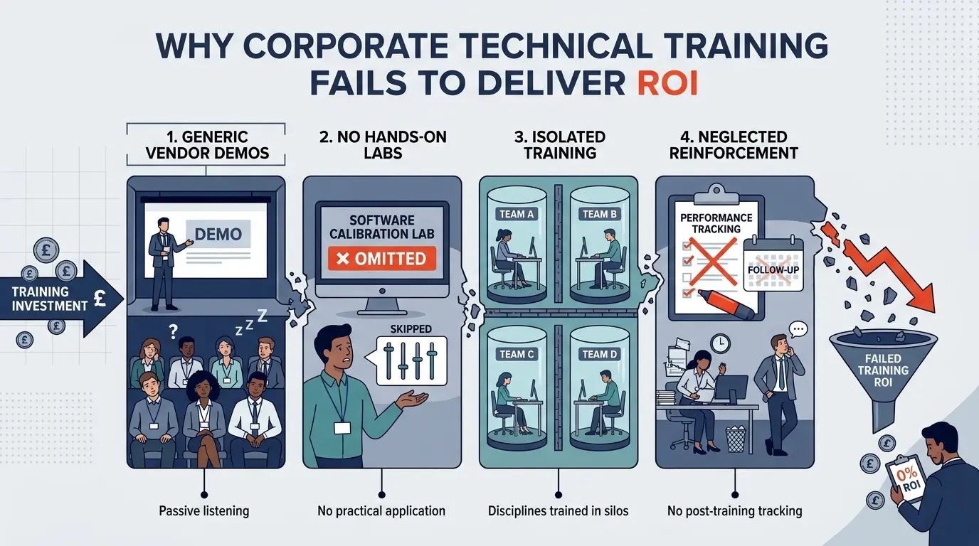
Learning and development leaders must avoid four structural pitfalls when designing and procuring subsurface technical training programmes.
Mistake 1: Confusing Vendor Tool Briefings with Competency Training
Service company sales presentations focus on proprietary hardware specifications rather than objective geological interpretation methodologies. Relying solely on vendor briefings leaves geoscientists unable to compare tool limitations or troubleshoot corrupted telemetry files independently. Effective corporate training maintains vendor-neutral objectivity, teaching fundamental physics and quality control standards applicable across all commercial logging platforms.
Mistake 2: Delivering Passive Lecture-Only Workshops
Theoretical lectures without interactive workstation exercises produce less than 15% skill retention after 30 days. Subsurface interpretation is a visual and analytical discipline that requires deliberate practice on messy, real-world datasets. Programmes must allocate at least 60% of instructional time to hands-on log processing, artefact identification, and structural mapping exercises.
Mistake 3: Training Subsurface Disciplines in Silos
Training petrophysicists without involving structural geologists, reservoir engineers, and drilling supervisors creates communication bottlenecks during live operations. When departments use inconsistent fracture classification terminology or misunderstand image resolution limits, integrated reservoir models suffer from conflicting inputs. Cross-functional cohorts foster collaboration and align technical workflows across the entire asset team.
Mistake 4: Neglecting Post-Training KPIs and Governance
Many organisations measure training success solely through post-course satisfaction surveys rather than operational performance indicators. Without structured 60-day and 90-day competency audits, employees revert to legacy interpretation habits under operational pressure. L&D managers must establish clear post-training KPIs, such as peer-review pass rates, interpretation turnaround times, and reduction in non-productive drilling time, to validate long-term organisational impact.
Frequently Asked Questions
What is Oil & Gas Borehole Imaging and how is it used in formation evaluation?
Oil & Gas Borehole Imaging is a high-resolution wireline and logging-while-drilling technique that captures detailed electrical, acoustic, or optical measurements of the wellbore wall to map subsurface rock formations. At the Institute For Oil & Gas Training, technical professionals learn to use these high-resolution image logs to identify natural fractures, bedding planes, fault orientations, and thin-bedded pay zones that conventional logging tools miss.
What is the difference between electrical and acoustic borehole imaging tools?
Electrical borehole imaging tools use pad-mounted micro-electrodes to measure formation resistivity contrasts, delivering superior vertical resolution down to 5 millimetres in conductive water-based muds. Acoustic borehole imagers emit ultrasonic pulses to measure travel time and amplitude reflections around the full 360-degree wellbore circumference, making them effective in non-conductive oil-based mud environments.
How does Oil & Gas Borehole Imaging reduce uncertainty in reservoir modelling?
Oil & Gas Borehole Imaging reduces subsurface geological uncertainty by providing oriented structural dip data, fracture aperture calculations, and depositional facies classifications directly from the borehole wall. Training programmes from the Institute For Oil & Gas Training equip geoscientists and petrophysicists to calibrate these high-resolution image logs against whole-core samples, ensuring accurate net-to-gross pay estimates and optimal well placement.
Which subsurface professionals require training in Oil & Gas Borehole Imaging?
Exploration geologists, development petrophysicists, reservoir engineers, geomechanics specialists, and drilling engineers require practical proficiency in Oil & Gas Borehole Imaging to support multidisciplinary asset decisions. Through structured workstation simulations offered by the Institute For Oil & Gas Training, cross-functional teams learn standardised quality control and interpretation workflows to reduce external consulting reliance.
How is borehole imaging data used to analyse wellbore stability and geomechanical stress?
Subsurface engineers analyse Oil & Gas Borehole Imaging logs to detect drilling-induced tensile fractures and borehole breakouts, which indicate the orientation and magnitude of present-day horizontal tectonic stresses. Understanding these geomechanical indicators allows drilling and completion teams to prevent wellbore collapse, mitigate mud losses, and design effective hydraulic fracturing stages.
For a practical walkthrough of wireline resistivity image interpretation, see the Introduction to Borehole Imaging and case study. This video demonstrates how petroleum geoscientists apply borehole imaging principles to real-world offshore formation analysis.
Related training courses
Acoustic Borehole Imaging Technologies Training Course
- Specialisation
- Oil & Gas Borehole Imaging
- Duration
- 5 days · 15 CPD hours
Borehole Image Interpretation for Paleocurrent Analysis Training Course
- Specialisation
- Oil & Gas Borehole Imaging
- Duration
- 5 days · 15 CPD hours
Borehole Image Interpretation for Bedding and Dip Analysis Training Course
- Specialisation
- Oil & Gas Borehole Imaging
- Duration
- 5 days · 15 CPD hours
More articles
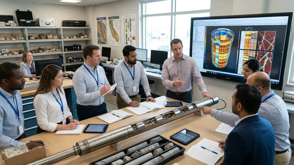
Electrical Borehole Imaging Technologies Training by Institute For Oil & Gas Training
Discover the curriculum, learning outcomes, and enrollment process for the Electrical Borehole Imaging Technologies Training Course.
Read article →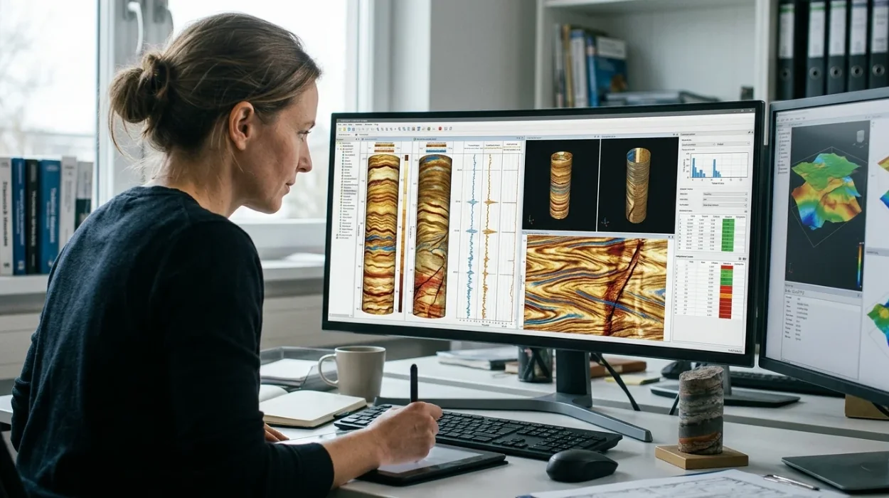
How to Evaluate Electrical Borehole Imaging Technologies and Their Applications in Formation Analysis
Master how to evaluate electrical borehole imaging technologies formation microimagers and resistivity logging tools for advanced subsurface analysis.
Read article →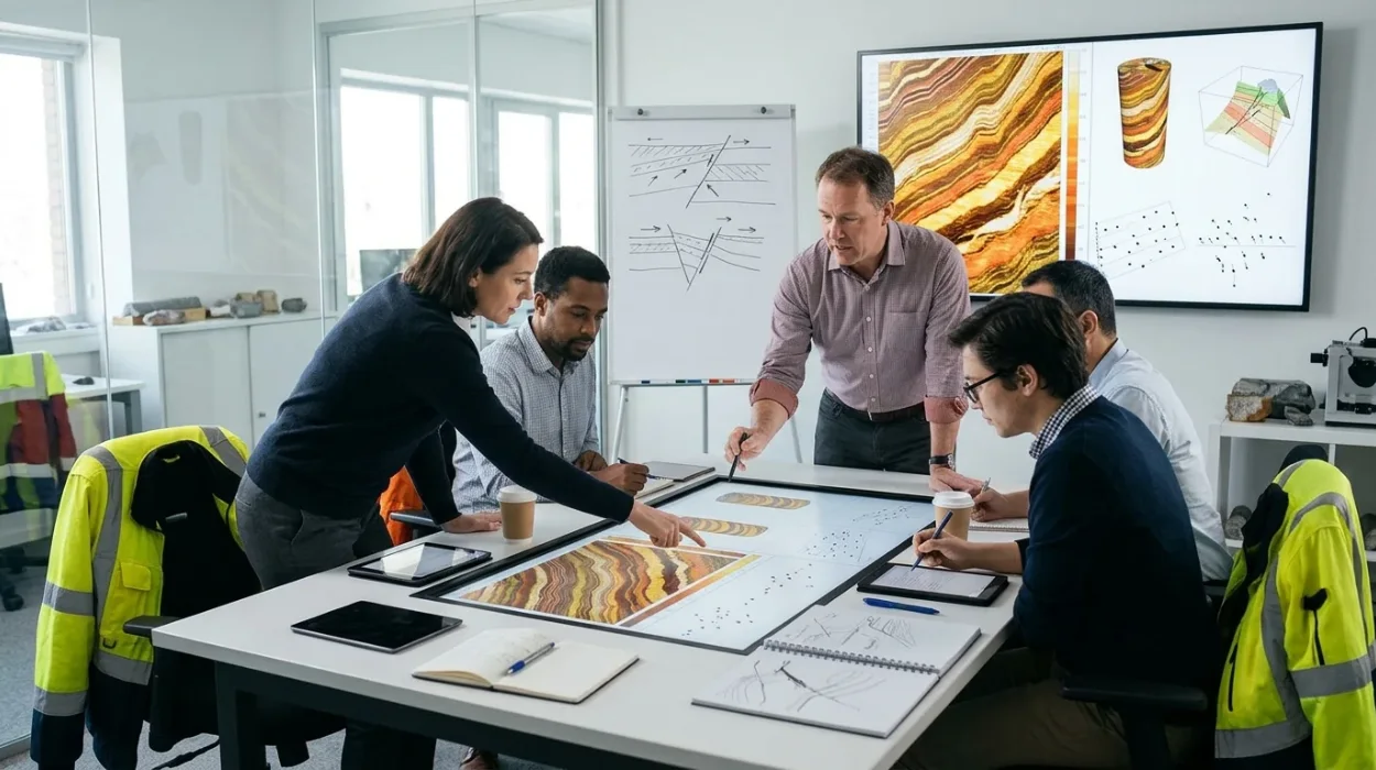
Dipmeter and Image Log Applications Training by Institute For Oil & Gas Training
Enrol in the Dipmeter and Image Log Applications Training Course by Institute For Oil & Gas Training to master structural dip and borehole image analysis.
Read article →