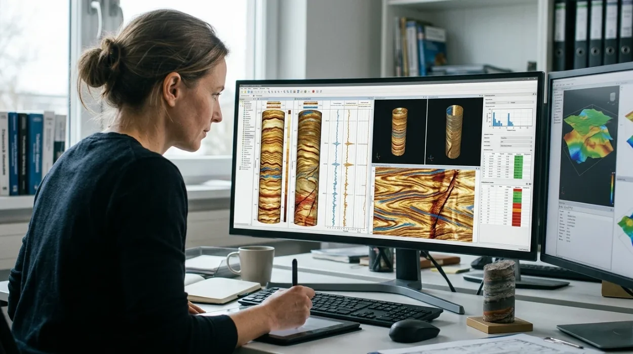
Subsurface evaluation requires precise diagnostic tools to map structural discontinuities, fracture networks, and sedimentary laminations in high resolution. Petrophysicists and asset teams rely on advanced logging suites to de-risk hydrocarbon exploration and carbon capture storage projects.
Understanding fundamental petrophysical principles underpins effective technology selection, which connects directly to broader geological insights found in How Electrical Borehole Imaging Improves Subsurface Geological Understanding. Asset managers must evaluate tool physics, operational constraints, and data processing capabilities before committing capital expenditure to specific logging suites.
What are the core parameters required to evaluate electrical borehole imaging technologies?
Evaluating electrical borehole imaging technologies demands rigorous assessment of vertical resolution, tool centralisation, mud resistivity contrasts, dynamic measurement range, total borehole coverage, and reliable sensor contact mechanics to ensure accurate micro resistivity mapping across complex heterogeneous geological formations and hostile environments.
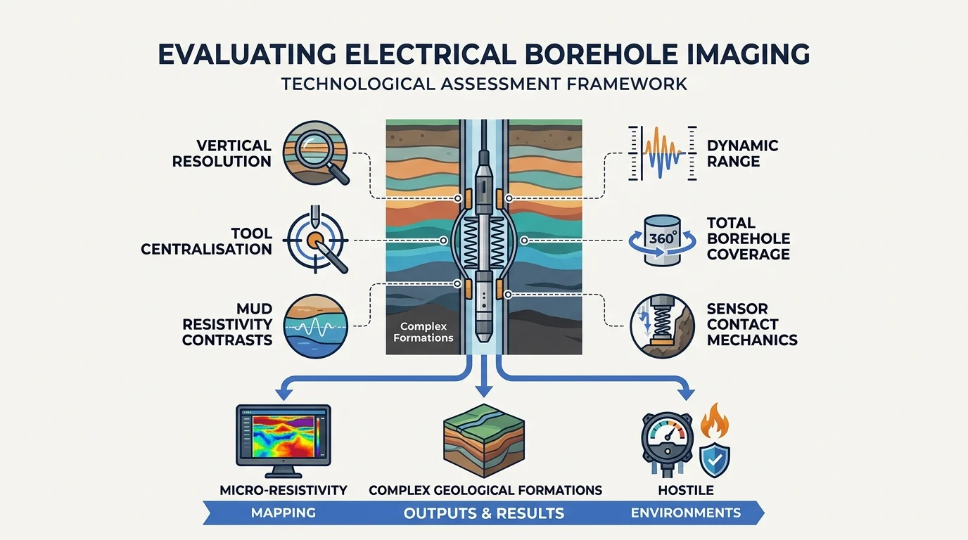
Electrical imaging tools operate by emitting electrical currents from button electrodes mounted on pads or collapsible arms into the borehole wall. The returning current map forms a high-resolution resistivity image that reveals textural variations, fracture orientation, and dip angles. Asset evaluation teams must analyze how well a given logging tool maintains signal fidelity under extreme downhole pressures and temperatures.
Electrical logging measurements depend heavily on the conductivity contrast between the drilling mud and the formation rock. When evaluating hardware options, engineering supervisors examine tool telemetry bandwidth, logging speed limitations, and button array density. Higher button density improves spatial resolution, but it requires superior telemetry channels to transmit massive data arrays without compression artifacts.
Workforce competency plays a critical role in this evaluation phase. HR training decisions within oil and gas operators often hinge on whether internal petrophysical teams possess the diagnostic capability to differentiate between genuine geological fractures and tool-induced borehole breakouts. Addressing workforce skill gaps prevents costly misinterpretations of subsurface structures during field development planning.
Learning delivery models must blend theoretical physics with software interpretation exercises. Organisations implement blended learning frameworks that combine classroom theory with workstation-based log analysis. Measuring return on investment requires tracking interpretation turnaround time, reduction in borehole re-evaluation cycles, and the accuracy of subsequent geological models delivered to drilling engineers.
How do different resistivity image logging tools compare across resolution and tool design?
Resistivity image logging tools differ fundamentally through pad versus cylinder configurations, electrode spacing density, button array placement, and operating frequencies, directly determining vertical resolution limits, azimuthal borehole coverage percentages, and qualitative performance in nonconductive oil based mud drilling fluid systems.
Selecting the appropriate imaging technology requires a direct comparison of physical tool architectures. Pad-based micro-resistivity devices offer superior vertical resolution, often resolving features down to a fraction of an inch. However, their azimuthal coverage is restricted by the physical dimensions of the pads, leaving blind spots between deployed arms unless centralized multi-pad configurations are deployed.
Conversely, wireline ultrasonic imaging tools and logging while drilling (LWD) electrical imagers offer full 360-degree borehole coverage, albeit with different resolution thresholds. LWD tools incorporate sensors directly into drill collars, enabling real-time borehole image acquisition while drilling. This capability allows geosteering teams to adjust well trajectories instantly based on structural dip indicators.
Evaluation Parameter | Pad-Based Micro-Resistivity | Wireline Ultrasonic Imager | LWD Electrical Imager |
Azimuthal Coverage | 40% to 80% (depending on pad count) | 360-degree full coverage | 360-degree full coverage |
Vertical Resolution | High (0.2 to 0.5 inches) | Moderate (0.5 to 1.0 inches) | Moderate to High (0.4 to 0.8 inches) |
Mud Compatibility | Water-based mud (optimised); specialized versions for oil-based mud | Water-based and oil-based muds | Water-based and oil-based muds |
Operational Timing | Wireline logging phase (post-drilling) | Wireline logging phase (post-drilling) | Real-time during drilling operations |
The comparative matrix above illustrates that no single tool dominates all operational scenarios. Asset managers evaluate formation lithology, mud system type, and time sensitivity before selecting a technology. For instance, in mature brownfields where wellbore stability is compromised, real-time LWD imagers provide vital structural insights before borehole degradation progresses.
Training programs must prepare subsurface engineers to interpret these disparate data formats. Standardising interpretation workflows across both wireline and LWD modalities ensures consistent geological evaluations. Corporate learning initiatives focus on bridging the gap between raw tool physics and final petrophysical deliverables, driving measurable performance improvements across asset teams.
What criteria define effective borehole image acquisition in complex lithologies?
Effective borehole image acquisition relies strictly on optimal logging speed control, precise mud weight calibration, robust standoff management, advanced telemetry transmission rates, and rigorous calibration procedures designed to eliminate motion artefacts and distortion across fractured carbonate and laminated sandstone reservoirs.
Acquiring pristine electrical images in complex lithologies demands strict adherence to operational protocols. In fractured carbonates, rugose boreholes frequently disrupt pad contact, leading to current bypass and washed-out image traces. Tool string design must incorporate articulated arms and heavy-duty spring mechanisms to maintain constant mechanical pressure against the borehole wall.
Mud properties dictate current injection efficiency. In oil-based mud environments, non-conductive continuous phases require high-frequency alternating current measurements combined with micro-pad induction techniques. Asset teams evaluate whether candidate tools incorporate advanced high-voltage circuitry capable of penetrating mud cake without losing formation signal definition.
Operational efficiency directly impacts corporate expenditure. Logging speed must remain within calibrated thresholds, typically between 1800 and 2500 feet per hour, to prevent vertical compression or stretching of image features. Exceeding these speed limits degrades spatial resolution and compromises fracture aperture calculations.
Workforce proficiency in quality control is essential for identifying acquisition anomalies. Personnel must distinguish between genuine geological laminations and logging speed variations, mud cake anomalies, or eccentric tool motion. Organisations invest in targeted training modules to ensure that field supervisors and petrophysicists audit raw data streams before handoff to reservoir modellers.
How do engineering teams bridge technical skill gaps when deploying advanced formation microimager systems?
Bridging technical skill gaps requires structured corporate learning frameworks, specialized technical workshops, practical petrophysical software training, and competency validation programs that equip multidisciplinary asset teams to interpret complex resistivity image logs with high analytical precision and operational strategic business confidence.
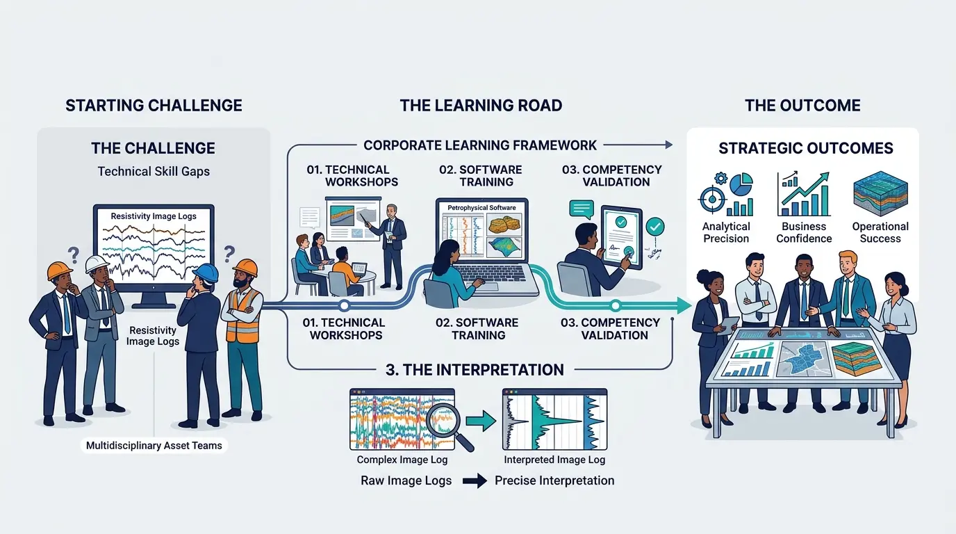
Organisations facing steep learning curves in advanced data interpretation deploy the Electrical Borehole Imaging Technologies Training by Institute For Oil & Gas Training to accelerate competency. This program addresses specific workforce gaps by translating complex log acquisition physics into actionable diagnostic workflows. HR leaders prioritize such initiatives to ensure measurable return on investment in technical assets.
Furthermore, enrolling staff in the Electrical Borehole Imaging Technologies Training Course establishes clear benchmarks for competency development, aligning technical execution with strategic corporate goals. Subsurface teams learn to integrate electrical image logs with core data, seismic interpretations, and production logs to build comprehensive reservoir models.
Learning delivery models must reflect the technical complexity of modern petroleum engineering. Effective training programs combine expert-led instruction with workstation exercises using real-world anonymised logging datasets. Participants evaluate fracture density, stress anisotropy, and depositional facies under simulated operational constraints.
Measuring the business impact of technical training involves tracking key performance indicators such as interpretation turnaround time, reduction in borehole re-evaluation cycles, and accuracy of sweet-spot identification in unconventional plays. When asset teams master advanced borehole imaging, exploration risk decreases and drilling success rates improve substantially across corporate portfolios.
Frequently Asked Questions
What is oil & gas borehole imaging and how does it work?
Oil & gas borehole imaging is an advanced logging technique that uses electrical or acoustic sensors to map the structural and textural properties of subsurface formations in high resolution. Through specialised programs offered by the Institute For Oil & Gas Training, professionals learn to interpret these detailed resistivity images to evaluate fracture networks and sedimentary laminations.
Why is borehole imaging important in formation evaluation?
Borehole imaging provides asset teams with critical data regarding dip angles, borehole stability, and localized geological anomalies that traditional open-hole logs might miss. By mastering these diagnostic frameworks through the Institute For Oil & Gas Training, petrophysicists can significantly reduce exploration risk and improve wellbore placement accuracy.
How do drilling mud systems affect oil & gas borehole imaging?
The conductivity of drilling fluids dictates whether pad-based micro-resistivity tools or ultrasonic imagers are required for effective data acquisition in a borehole. Engineers trained at the Institute For Oil & Gas Training carefully evaluate these mud-tool compatibility factors to ensure pristine image quality and prevent costly interpretation errors.
How can energy companies bridge skill gaps in borehole image interpretation?
Organisations can overcome complex data interpretation challenges by implementing structured workforce development frameworks and practical workstation training. The Institute For Oil & Gas Training delivers targeted oil & gas borehole imaging programs that equip multidisciplinary teams to analyze structural discontinuities with absolute confidence.
What is the difference between wireline and LWD borehole imaging?
Wireline borehole imaging is conducted post-drilling to capture high-resolution downhole measurements, whereas logging-while-drilling (LWD) provides real-time structural data while drilling operations are active. Understanding both deployment modalities is a core competency emphasized in professional training at the Institute For Oil & Gas Training.
Related training courses
Advanced Borehole Image Interpretation Training Course
- Specialisation
- Oil & Gas Borehole Imaging
- Duration
- 5 days · 15 CPD hours
Borehole Image Analysis for In-Situ Stress Evaluation Training Course
- Specialisation
- Oil & Gas Borehole Imaging
- Duration
- 5 days · 15 CPD hours
Borehole Image Applications for Reservoir Characterization Training Course
- Specialisation
- Oil & Gas Borehole Imaging
- Duration
- 5 days · 15 CPD hours
More articles
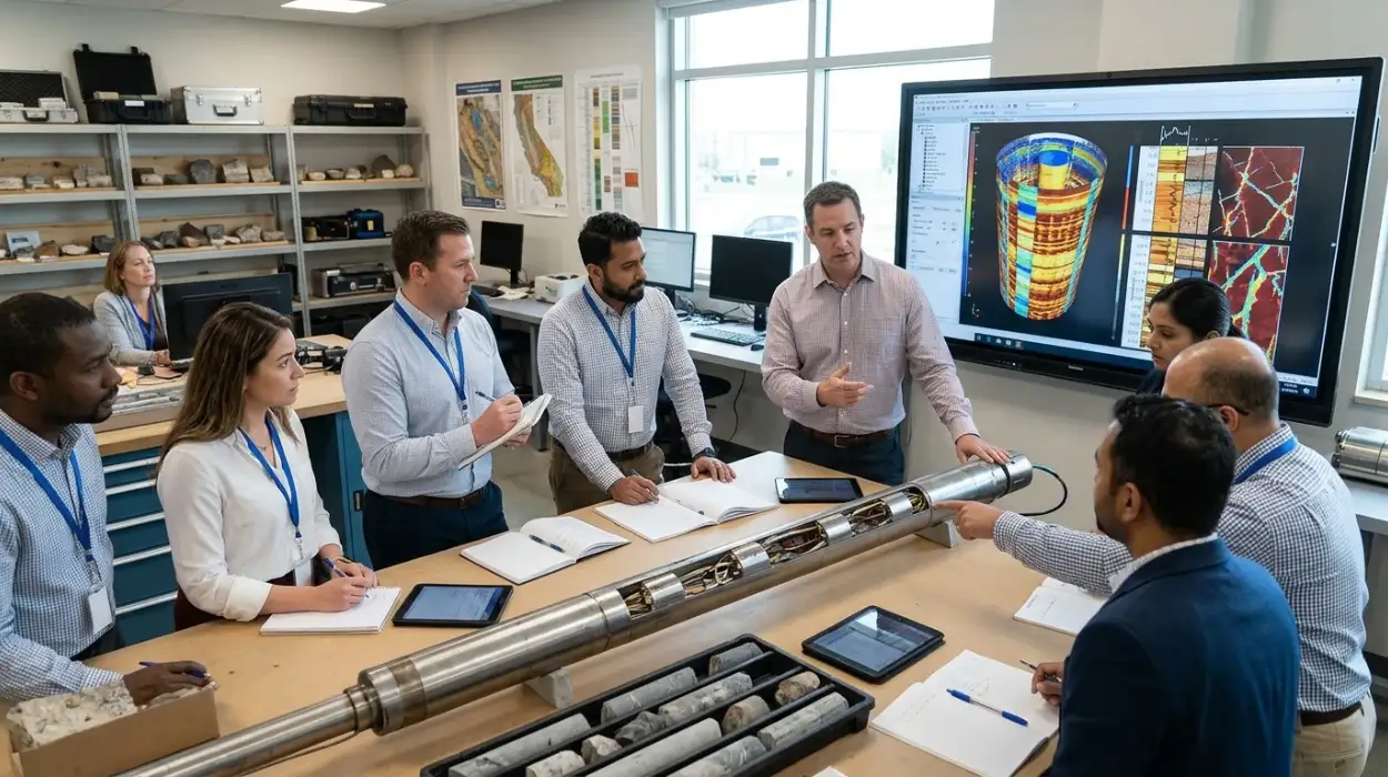
Electrical Borehole Imaging Technologies Training by Institute For Oil & Gas Training
Discover the curriculum, learning outcomes, and enrollment process for the Electrical Borehole Imaging Technologies Training Course.
Read article →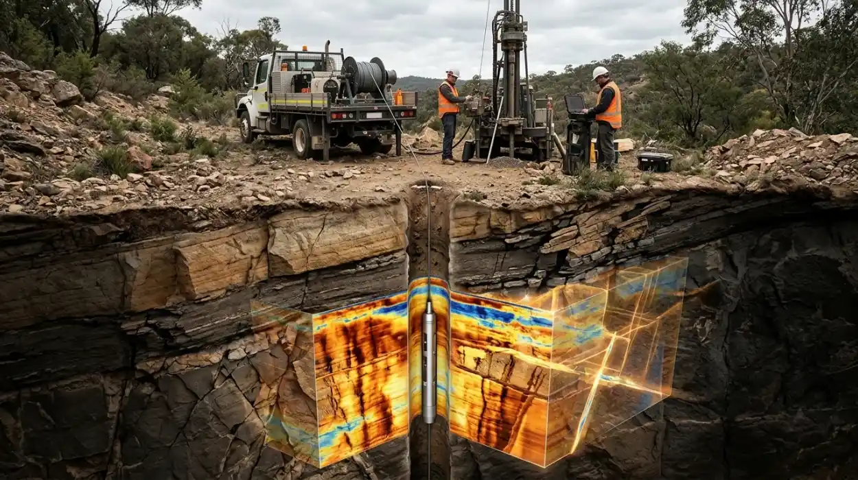
How Electrical Borehole Imaging Improves Subsurface Geological Understanding
Learn how electrical borehole imaging improves subsurface geological understanding and workforce competency through structured corporate technical training.
Read article →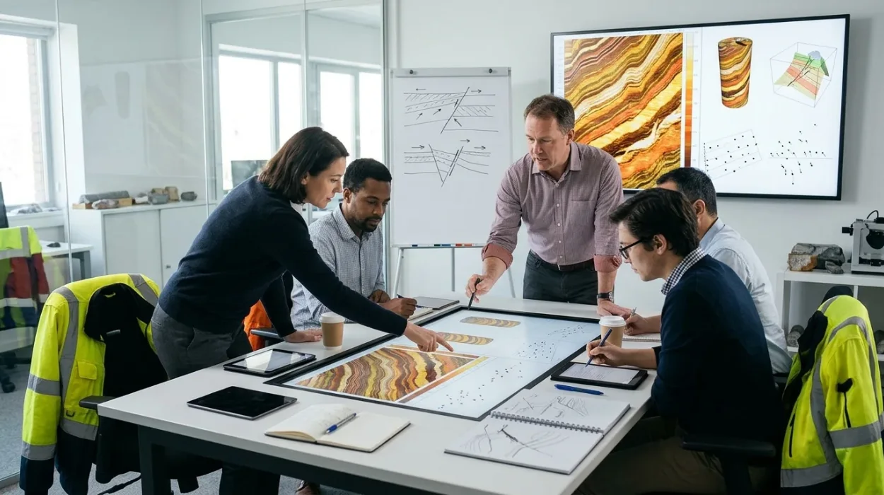
Dipmeter and Image Log Applications Training by Institute For Oil & Gas Training
Enrol in the Dipmeter and Image Log Applications Training Course by Institute For Oil & Gas Training to master structural dip and borehole image analysis.
Read article →