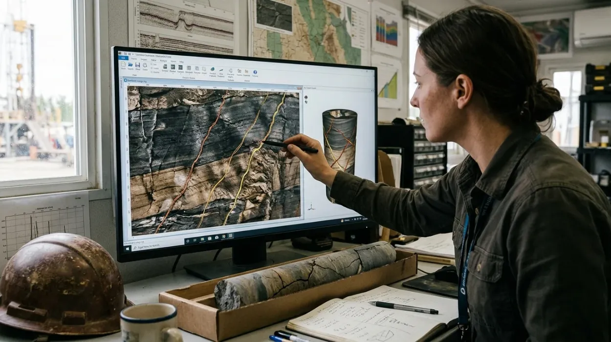
Borehole image logs are high-resolution circumferential measurements of the wellbore wall acquired through electrical or acoustic sensors to map geological features. For energy organisations, workforce mastery of these logs eliminates costly drilling errors, optimises well placement, and maximises hydrocarbon recovery.
Borehole image logs convert physical properties of rock formations into two-dimensional unwrapped representations of the cylindrical borehole wall. Subsurface teams rely on these digital datasets to view structural dips, sedimentary textures, and fracture networks at millimetre-scale resolution. Without specialised workforce training in borehole image interpretation, exploration and production companies misread reservoir connectivity and drill unprofitable wells.
Conventional open-hole wireline logs such as gamma ray, resistivity, and sonic tools average rock properties across large vertical intervals ranging from 0.5 metres to 2 metres. These low-resolution measurements miss thin, high-permeability fracture networks that control fluid flow in tight formations and carbonate reservoirs. Training geoscientists and reservoir engineers to process and interpret high-resolution image data bridges this critical diagnostic gap.
From a corporate asset management perspective, sub-optimal fracture characterisation directly inflates capital expenditure. Drilling a single offshore appraisal well costs between $30 million and $100 million, and misinterpreting fracture orientation leads to wellbore collapse or premature water breakthrough. Upskilling technical teams ensures that multi-million-dollar drilling decisions rest on verified structural data rather than geological assumptions.
How Does Corporate Training in Borehole Image Interpretation Work?
Corporate training in borehole image interpretation operates through structured, multi-stage technical curricula combining theoretical rock mechanics with hands-on software simulations. Organisations implement this training via modular workshops and blended learning pathways to align geoscience teams with operational asset workflows.
Learning and development (L&D) departments structure technical upskilling around the actual lifecycle of a subsurface evaluation project. Rather than relying on passive lectures, effective programmes replicate the daily workstation environment of an operating oil and gas company. Participants work directly with raw field datasets from global basins, moving sequentially from data quality control to final structural modelling.
Step 1: Skill Gap Assessment and Baseline Diagnostic Testing
Organisations initiate the training process by auditing current team capabilities against asset complexity. L&D managers administer practical baseline assessments covering well logging physics, stereonet projection reading, and geomechanical stress principles. These diagnostic tests identify specific knowledge deficits across junior petrophysicists, operations geologists, and reservoir engineers, allowing instructors to calibrate module difficulty.
Step 2: Delivery Formats and Applied Learning Methodologies
Technical training providers deliver these programmes through three primary formats tailored to corporate schedules:
Intensive Five-Day Instructor-Led Workshops: Delivered on-site at corporate headquarters or regional operational hubs, enabling direct collaboration between cross-functional asset teams.
Blended Cohort Programmes: Combining 15 hours of self-paced digital modules on tool physics with 20 hours of live virtual workstation labs over a four-week period.
Project-Based Simulation Labs: Immersive workshops where participants interpret proprietary company well logs alongside industry benchmark datasets to solve real-world drilling challenges.
During these sessions, case-based learning replaces theoretical abstraction. Learners evaluate actual field failures, such as lost circulation events caused by unmapped conductive fractures, and build corrective interpretation workflows.
Step 3: Post-Training Competency Verification and Workplace Integration
Training concludes with graded capstone evaluations where participants deliver a complete fracture characterisation report for a benchmark well. Line managers then integrate these newly acquired workflows into standard operating procedures (SOPs) for well planning and peer-review gates. If your technical team is currently evaluating structured learning pathways to build hands-on diagnostic workflows, explore how to identify and evaluate natural and induced fractures using borehole image logs to align curriculum standards with operational asset requirements.
What Core Components Must a Borehole Image Log Training Curriculum Include?
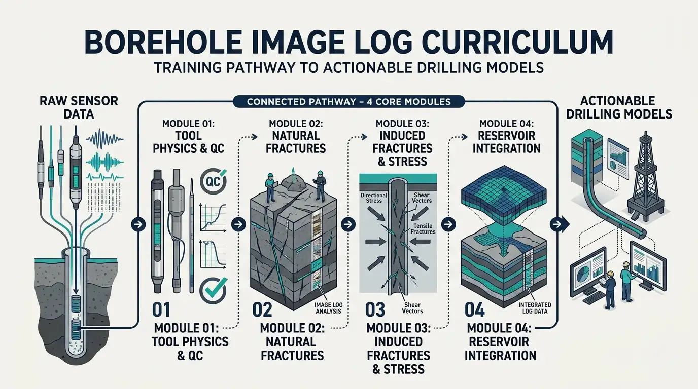
A comprehensive borehole image log curriculum includes four core technical components: tool physics and quality control, natural fracture identification, induced fracture and stress analysis, and reservoir integration. Mastering these modules equips teams to translate raw sensor data into actionable drilling models.
HR managers and technical team leaders must verify that training curricula balance foundational physics with commercial software execution. Omitting quality control or geomechanical context produces technicians who generate visually appealing plots with flawed geological conclusions.
1. Sensor Physics and Data Quality Control (QC)
Teams first learn the operational mechanics of electrical micro-resistivity tools and acoustic ultrasonic televiewers. Electrical tools measure micro-resistivity contrasts using pad-mounted buttons pressed against the borehole wall, performing best in conductive water-based muds. Acoustic tools emit high-frequency ultrasonic pulses and record amplitude and travel-time reflections, operating effectively in both water-based and oil-based drilling fluids.
Participants learn to detect and correct acquisition artefacts before interpretation begins:
Stick-and-Pull Artefacts: Depth distortions caused by irregular tool movement during wireline logging runs, corrected using accelerometer speed data.
Pad Lift-Off and Washouts: Signal loss occurring when borehole enlargement prevents sensor pads from contacting the formation wall.
Eccentering Effects: Asymmetric amplitude banding in acoustic logs caused by the logging tool resting off-centre in deviated wellbores.
2. Natural Fracture Identification and Aperture Quantification
Natural fractures represent pre-existing geological discontinuities formed by tectonic forces, regional folding, or diagenetic processes. Training teaches interpreters to distinguish between open conductive fractures, which appear as dark sinusoidal traces filled with conductive drilling mud, and cemented resistive fractures, which appear as bright sinusoidal traces filled with calcite or quartz.
Learners also calculate fracture aperture—the physical width of the open void—using calibrated resistivity equations. Accurately quantifying aperture separates minor hairline cracks from high-permeability conduits capable of delivering thousands of barrels of oil per day.
3. Induced Fractures and Geomechanical Stress Mapping
Drilling operations alter the natural stress state around the borehole, creating drilling-induced tensile fractures and borehole breakouts. Induced fractures form parallel to the maximum horizontal stress direction when mud weight exceeds the tensile strength of the rock. Borehole breakouts occur 90 degrees away, parallel to the minimum horizontal stress direction, where compressive rock failure spalls the wellbore wall.
Training teams to map these induced features delivers immediate operational value. Interpreters determine the exact orientation of the present-day in-situ stress field, enabling drilling engineers to optimise mud weight windows and prevent catastrophic wellbore instability.
4. Fracture Orientation Analysis and Reservoir Simulation Integration
Raw sinusoid picks hold minimal business value until converted into three-dimensional structural metrics. Curricula train geoscientists to plot fracture orientation data onto stereonets and rose diagrams to identify dominant fracture sets. Teams then compute fracture intensity logs (P10, P21, and P32 metrics) that feed directly into discrete fracture network (DFN) models used by reservoir engineers to simulate fluid flow and plan horizontal well trajectories.
What Measurable Business Benefits Does Fracture Detection Training Deliver?
Technical training in fracture detection delivers measurable reductions in non-productive time, higher hydrocarbon recovery rates, and improved cross-departmental decision speed. Organisations achieve a quantifiable return on investment by preventing drilling hazards and optimising well completion designs.
For corporate decision-makers, L&D investments must demonstrate clear financial and operational returns. Upskilling subsurface teams through a dedicated Borehole Image Logs for Fracture Detection Training Course directly impacts key performance indicators (KPIs) across drilling, reservoir engineering, and asset management.
Operational Metric / KPI | Pre-Training Baseline Challenge | Post-Training Measurable Outcome |
Non-Productive Time (NPT) | Unanticipated mud losses and stuck pipe in fractured zones | 15% to 25% reduction in wellbore instability NPT |
Well Trajectory Efficiency | Horizontal wells drilled parallel to main fracture sets | 30% to 45% increase in intersected open fractures |
Interpretation Cycle Time | External consultant dependency adding 3–4 weeks per well | 50% faster in-house log-to-model turnaround time |
Completion Capital Allocation | Uniform hydraulic fracturing across non-productive intervals | 10% to 20% reduction in wasted completion stage costs |
Beyond direct cost avoidance, internal capability development strengthens organisational resilience. Retaining skilled petrophysicists and structural geologists reduces reliance on third-party service company interpretations, keeping proprietary geological intelligence inside the company. Furthermore, standardised interpretation terminology eliminates friction during peer-review meetings between geology, geophysics, and drilling departments.
Which Corporate Teams and Industry Sectors Benefit Most from This Training?
Upstream oil and gas operators, geothermal energy developers, carbon capture firms, and subsurface engineering consultancies gain the highest operational value from this training. Within these organisations, petrophysicists, operations geologists, drilling engineers, and reservoir engineers apply these skills daily.
While traditionally anchored in conventional hydrocarbon exploration, borehole image interpretation has expanded rapidly across multiple energy transition sectors. HR directors and technical managers deploy this training across diverse operational units:
Carbonate Reservoir Asset Teams: Carbonate rocks hold over 60% of global oil reserves and 40% of global gas reserves, yet their matrix permeability is often negligible. Asset teams managing fractured carbonate reservoirs rely entirely on image logs to locate productive fracture corridors and avoid early water coning.
Unconventional Shale and Tight Gas Teams: Subsurface teams in basins like the Permian or Vaca Muerta use induced fracture orientation to map local stress variations, ensuring hydraulic fracture stages propagate efficiently without communicating with adjacent wells.
Enhanced Geothermal Systems (EGS) Developers: Geothermal operators drill into crystalline basement rocks where heat extraction depends entirely on fluid circulation through natural fracture networks. Trained geoscientists map permeable fault zones to connect injection and production wells.
Carbon Capture, Utilisation, and Storage (CCUS) Teams: Storage engineers evaluate caprock integrity above saline aquifers. Image logs confirm the absence of open, conductive fractures that could breach the top seal and allow injected carbon dioxide to migrate upward.
Within a typical corporate asset team, cross-training produces the strongest collaborative results. When drilling engineers understand how operations geologists identify borehole breakouts in real time, both groups adjust drilling parameters immediately rather than waiting for post-well reviews.
What Common Misconceptions and Implementation Pitfalls Derail Corporate Training?
Corporate training fails when organisations rely on generic software tutorials, skip real-world field datasets, or exclude drilling engineers from geoscience workshops. Avoiding these implementation errors ensures technical knowledge transfers directly to active subsurface projects.
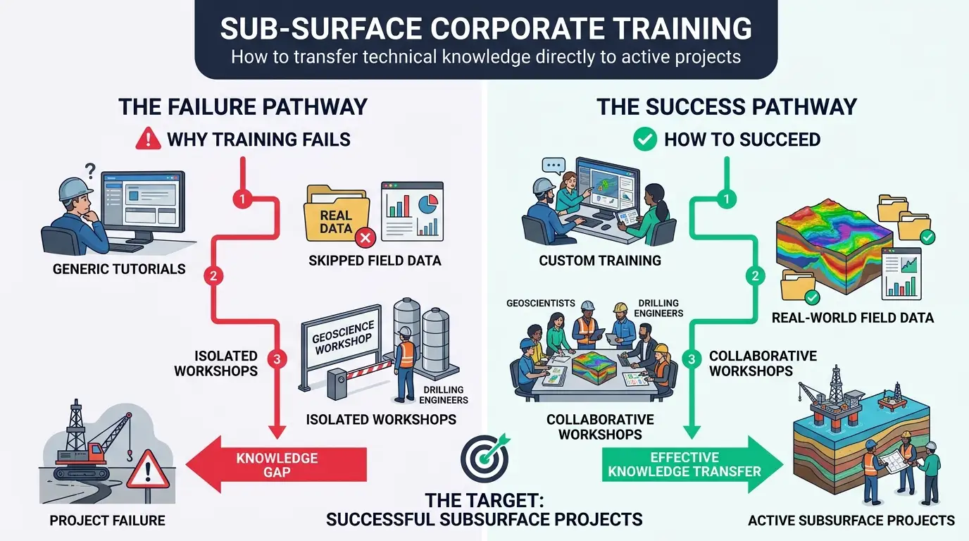
L&D leaders frequently invest in technical courses that yield high classroom satisfaction scores yet produce zero measurable change in workplace performance. Five common pitfalls undermine borehole image interpretation training:
Confusing Software Button-Pushing with Geological Interpretation: Vendor-led software training teaches users where menu buttons sit, not how to distinguish a drilling-induced tensile fracture from a natural open fracture. Effective training prioritises geological principles and rock mechanics before touching software interfaces.
Using Clean Textbook Examples Instead of Noisy Field Logs: Commercial datasets from active oilfields contain mud cake irregularities, tool stick-and-pull distortions, and complex lithological variations. Training teams solely on idealised textbook images leaves interpreters unprepared for messy operational data.
Siloing Training by Job Title: Training petrophysicists in isolation prevents shared understanding across the asset team. Including reservoir engineers and drilling engineers in core interpretation modules builds a unified technical vocabulary and accelerates multidisciplinary collaboration.
Neglecting Post-Course Application Windows: Technical skills decay by up to 70% within 30 days if not applied immediately. L&D managers must schedule training cohorts immediately prior to active drilling campaigns or field development studies so learners apply workflows on live wells.
Overlooking Core-to-Log Calibration Workflows: Image logs measure indirect physical responses, not actual rock samples. Programmes that fail to teach how to calibrate image features against physical slabbed core data foster overconfidence in unverified digital picks.
Addressing these structural gaps transforms corporate training from an annual compliance expense into a high-impact operational driver. When subsurface teams possess validated, standardised skills in borehole image analysis, organisations de-risk capital allocation, protect wellbore integrity, and extract maximum value from complex reservoirs.
Frequently Asked Questions
What is Oil & Gas Borehole Imaging used for in reservoir evaluation?
Oil & Gas Borehole Imaging generates high-resolution electrical and acoustic images of the wellbore wall to map structural dips, sedimentary features, and fracture networks. Through specialised technical courses at the Institute For Oil & Gas Training, geoscientists learn to evaluate reservoir heterogeneity and permeability pathways that conventional wireline logs miss.
How do borehole image logs distinguish natural fractures from drilling-induced fractures?
Natural fractures appear as continuous sinusoidal traces crossing the borehole wall at varying dip angles, whereas drilling-induced tensile fractures form vertically aligned pairs parallel to the maximum horizontal stress direction. Training in Oil & Gas Borehole Imaging equips interpreters to separate productive open fractures from stress-induced wellbore failure to improve drilling safety.
Which wireline tools are used for Oil & Gas Borehole Imaging?
Subsurface teams primarily use micro-resistivity pad tools for conductive water-based muds and ultrasonic acoustic televiewers for oil-based or non-conductive drilling fluids. The Institute For Oil & Gas Training covers both sensor technologies, enabling petrophysicists and operations geologists to select the right logging tool and perform accurate quality control.
Why is Oil & Gas Borehole Imaging important for fractured carbonate reservoirs?
Carbonate reservoirs often exhibit low matrix permeability, meaning fluid flow relies heavily on interconnected natural fracture networks and vuggy porosity. Oil & Gas Borehole Imaging identifies open fracture apertures and orientations, allowing reservoir engineers to optimise horizontal well placement and maximise hydrocarbon recovery.
Who should attend training in Oil & Gas Borehole Imaging?
Operations geologists, petrophysicists, structural geologists, reservoir engineers, and drilling engineers benefit directly from mastering borehole image interpretation. Programmes delivered by the Institute For Oil & Gas Training provide cross-functional asset teams with standardised workflows to reduce non-productive time and de-risk field development decisions.
Related training courses
Borehole Image Applications in Sedimentology Training Course
- Specialisation
- Oil & Gas Borehole Imaging
- Duration
- 5 days · 15 CPD hours
Borehole Image Interpretation for Paleocurrent Analysis Training Course
- Specialisation
- Oil & Gas Borehole Imaging
- Duration
- 5 days · 15 CPD hours
Borehole Image Applications in Clastic and Carbonate Reservoirs Training Course
- Specialisation
- Oil & Gas Borehole Imaging
- Duration
- 5 days · 15 CPD hours
More articles
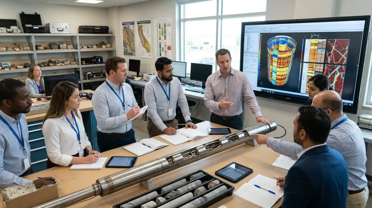
Electrical Borehole Imaging Technologies Training by Institute For Oil & Gas Training
Discover the curriculum, learning outcomes, and enrollment process for the Electrical Borehole Imaging Technologies Training Course.
Read article →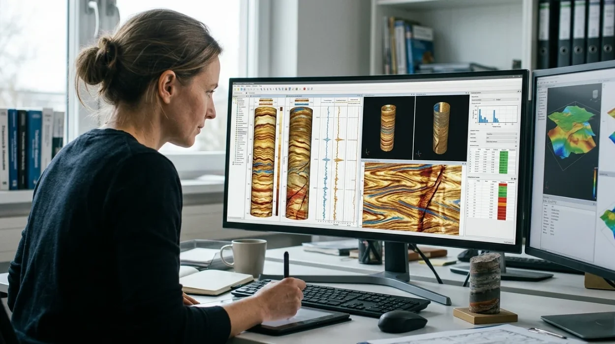
How to Evaluate Electrical Borehole Imaging Technologies and Their Applications in Formation Analysis
Master how to evaluate electrical borehole imaging technologies formation microimagers and resistivity logging tools for advanced subsurface analysis.
Read article →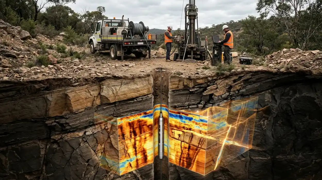
How Electrical Borehole Imaging Improves Subsurface Geological Understanding
Learn how electrical borehole imaging improves subsurface geological understanding and workforce competency through structured corporate technical training.
Read article →