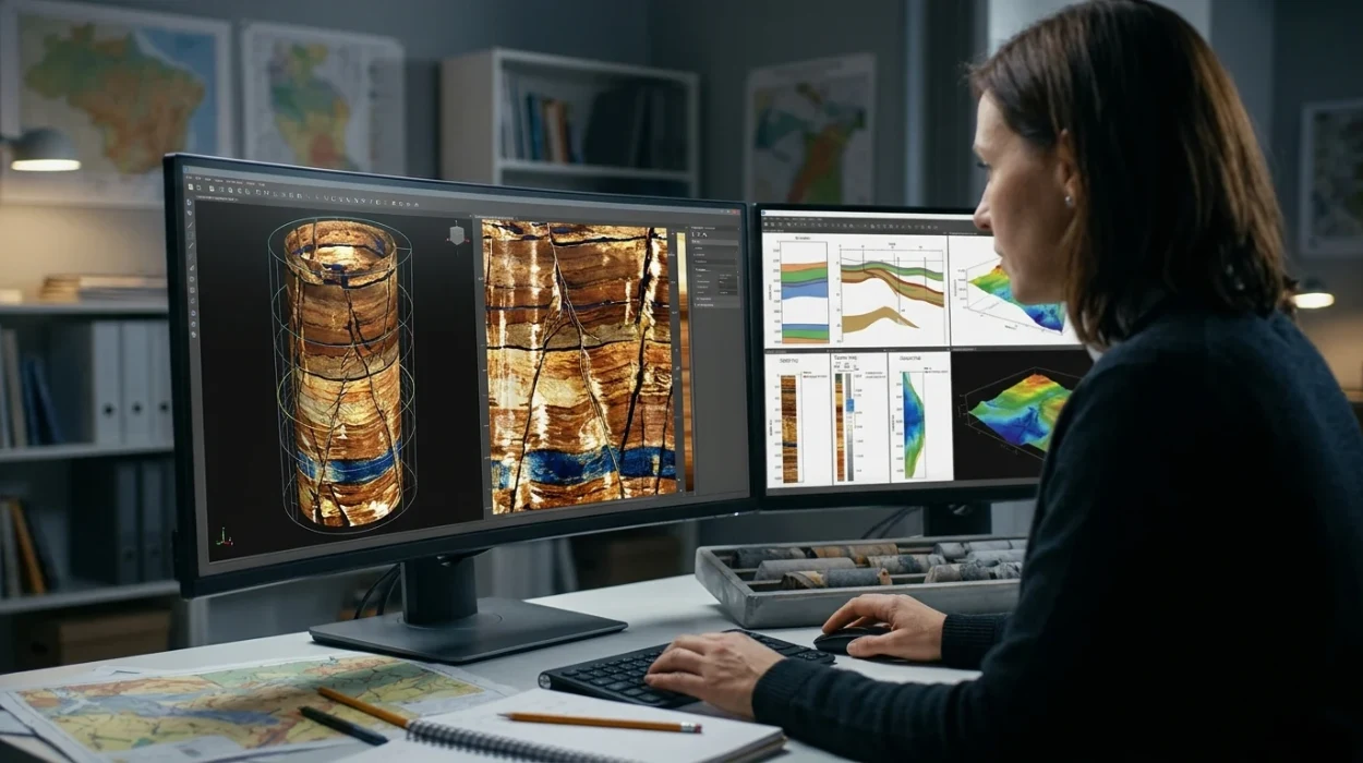
Advanced borehole image interpretation is a specialised geoscience discipline that converts high-resolution electrical and acoustic wellbore measurements into structural, stratigraphic, and geomechanical geological models, enabling energy organisations to reduce drilling uncertainty, eliminate costly coring operations, and improve hydrocarbon recovery rates.
In corporate upstream environments, subsurface teams rely on wireline and logging-while-drilling (LWD) imaging tools to capture micro-resistivity and ultrasonic reflections around the borehole wall. These raw digital datasets replace expensive whole-core retrieval, which costs energy operators between £150,000 and £400,000 per well depending on offshore rig rates. When geoscientists lack structured training in decoding these images, companies misidentify pay zones, misplace horizontal well trajectories, and forfeit millions in recoverable reserves.
From a Learning and Development (L&D) perspective, advanced borehole image interpretation represents a high-value technical competency within corporate capability frameworks. It bridges the operational divide between raw petrophysical data acquisition and integrated reservoir characterisation. Human Resources (HR) managers and subsurface team leaders treat this capability as a core operational safeguard rather than an optional academic skill.
Organisations that institutionalise this expertise establish clear competency matrices across three technical tiers:
Foundation Tier: Basic quality control, tool physics comprehension, and primary dip picking.
Practitioner Tier: Detailed bedding interpretation, fracture analysis, and identification of sedimentary structures.
Specialist Tier: Paleocurrent mapping, borehole breakout stress modelling, and multi-well static reservoir integration.
When subsurface departments standardise these definitions across asset teams, technical review boards evaluate geological interpretations using objective, auditable criteria rather than subjective individual estimates.
How Does Corporate Training in Borehole Image Interpretation Work?
Corporate training in advanced borehole image interpretation operates through a structured, competency-based learning lifecycle that diagnoses technical skill gaps, delivers workstation-driven practical modules, and measures workplace transfer through audited geological interpretation projects within active company asset teams.
Enterprise training delivery moves away from passive lecture formats because geoscientists retain less than 15% of purely theoretical instruction after 30 days. Instead, L&D departments deploy a four-stage operational framework tailored to corporate schedules and asset deadlines.
Stage 1: Technical Competency Benchmarking and Gap Analysis
Before instruction begins, technical leads and L&D specialists administer a diagnostic assessment using blind well datasets. Geoscientists complete a 4-hour practical test involving dip classification, artifact recognition, and structural zonation. Results establish baseline accuracy scores, revealing whether errors stem from poor tool physics knowledge or flawed geological modelling workflows.
Stage 2: Blended and Hybrid Delivery Execution
Organisations structure delivery across hybrid learning formats to minimise operational downtime for active asset teams:
Intensive Corporate Workshops: 5-day instructor-led cohorts (35 to 40 instructional hours) conducted on-site or at dedicated technical centres.
Modular Virtual Cohorts: 10 half-day live sessions spread across 5 weeks, allowing exploration and development teams in different time zones to participate without halting daily well operations.
Self-Paced Digital Simulations: Cloud-hosted software environments providing 24/7 access to annotated global well logs for asynchronous skill reinforcement.
Stage 3: Case-Based Workstation Simulations
Participants spend 70% of instructional time working directly inside industry-standard petrophysical interpretation platforms. Rather than analysing simplified textbook diagrams, learners process noisy, real-world datasets from complex geological settings across sectors such as upstream oil and gas, geothermal energy, and carbon capture and storage (CCS). Teams work in pairs to build structural cross-sections, defend their fracture classifications during peer-review role plays, and reconcile image logs with conventional triple-combo wireline suites.
Stage 4: Workplace Integration and Post-Training Audits
True corporate capability requires structured post-course transfer. Within 60 days of completing an Advanced Borehole Image Interpretation Training Course, participants apply the standardised workflow to an active company well. Senior technical advisors audit the resulting interpretation report against a 25-point quality assurance rubric, verifying that training methodologies translate directly into reliable business decisions.
What Are the Key Components of an Enterprise Borehole Image Training Program?
An effective enterprise borehole image training program integrates four core pillars: tool physics and quality control frameworks, structural and stratigraphic analytical methodologies, industry-standard workstation software proficiency, and quantitative key performance indicators (KPIs) that verify interpretation accuracy.
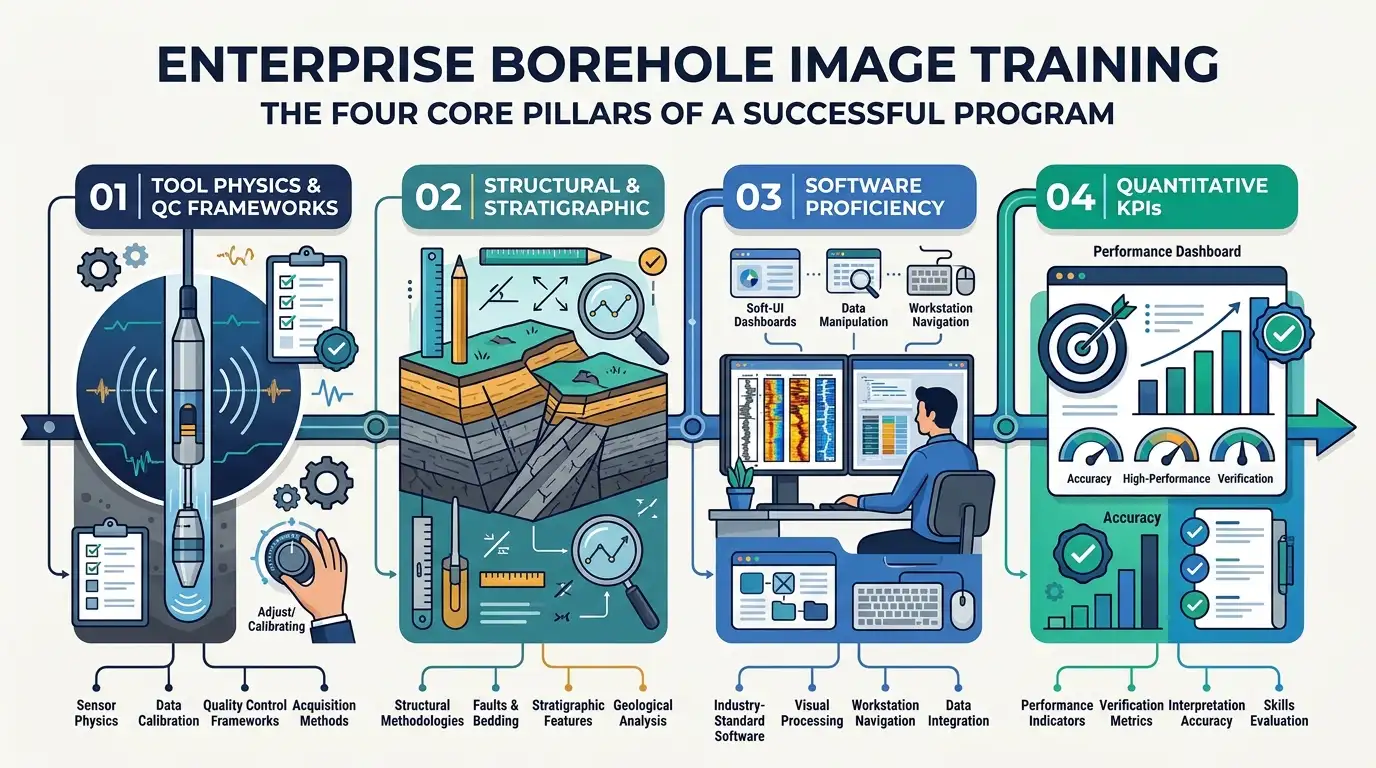
Corporate decision-makers evaluating technical curricula must verify that every program component maps directly to operational deliverables. Missing any single pillar creates bottlenecks where geoscientists generate visually appealing plots that fail engineering scrutiny during well planning.
Program Component | Core Technical Subjects | Corporate Deliverable | Verification Metric |
Acquisition & QC Physics | Micro-resistivity vs. ultrasonic sensors, pad contact artifacts, stick-slip correction, speed correction | Audited, depth-matched image log ready for geological picking | 100% identification of tool-induced artifacts prior to interpretation |
Structural & Fracture Analysis | Sinusoid fitting, conductive vs. resistive fractures, drilling-induced tensile fractures, borehole breakouts | Quantitative fracture density logs and maximum horizontal stress orientation | Less than 5-degree variance in structural dip azimuth against core data |
Sedimentology & Stratigraphy | Bedding interpretation, cross-bedding, sedimentary structures, paleocurrent mapping, unconformities | High-resolution depositional facies scheme and sand-body geometry prediction | 85% or higher facies classification agreement with whole-core descriptions |
Reservoir Integration | Electrofacies clustering, permeability modeling, thin-bed net-to-gross calculation, 3D model population | Updated static reservoir grid and refined horizontal well landing targets | 15% to 25% improvement in net-pay thickness calculation accuracy |
Tool Physics and Quality Control Frameworks
Geoscientists must distinguish genuine geological features from logging artifacts before picking a single dip. Training covers galvanic current focusing in oil-based versus water-based mud systems, acoustic transit-time attenuation, and accelerometer speed corrections. Mastery of quality control prevents teams from mistaking mudcake ridges or centralization errors for natural open fractures.
Structural and Sedimentological Methodologies
Programs establish strict classification hierarchies for planar and non-planar features. Learners apply systematic dip-picking protocols to separate regional structural tilt from local sedimentary structures such as trough cross-bedding, slumps, and scour surfaces. By removing structural dip mathematically, teams perform accurate paleocurrent mapping to predict reservoir sand pinch-outs and channel orientations away from the wellbore.
Geomechanical and Fracture Characterisation
In fractured carbonate and tight basement reservoirs, production depends entirely on natural fracture networks. Curricula train specialists to differentiate open, hydrocarbon-bearing fractures from cemented, resistive fractures. Participants also map borehole breakouts and drilling-induced tensile fractures to constrain the present-day in-situ stress tensor, providing drilling engineers with critical wellbore stability parameters.
Learning Methodologies and Assessment Rubrics
High-impact corporate courses replace multiple-choice exams with practical milestone assessments. Participants complete timed interpretation sprints, participate in cross-disciplinary role-play sessions acting as asset geologists defending well proposals to drilling managers, and receive granular feedback on their sinusoid-picking consistency. For L&D leaders building internal curricula, exploring how to apply advanced interpretation techniques to complex borehole image data provides a clear blueprint for structuring these technical exercises.
What Measurable Organisational Benefits Does Borehole Image Training Produce?
Organisations that invest in structured borehole image interpretation training achieve a 20% to 35% reduction in geological sidetrack rates, cut physical coring budgets by up to 50%, accelerate well-placement decisions by 40%, and improve technical staff retention by 18% annually.
Training budgets require rigorous financial justification. When HR directors and subsurface vice presidents evaluate technical training investments, they measure return on investment (ROI) across four operational dimensions.
Reduction in Non-Productive Time (NPT) and Sidetrack Costs
Drilling a geological sidetrack offshore costs between £2 million and £8 million per event. Misinterpreting fault drag or sub-seismic unconformities causes drill bits to exit target reservoir zones prematurely. Trained geoscientists identify subtle structural dip progressions in real time using LWD image logs, enabling directional drillers to steer wells back into optimal pay zones before drilling out of the reservoir.
Direct Capital Expenditure Savings on Core Acquisition
Physical coring requires dedicated rig trips, specialized barrels, and months of laboratory analysis. High-resolution borehole images calibrated with targeted sidewall cores deliver continuous, oriented geological data across 100% of the logged interval. Organisations with certified internal interpreters reduce whole-core acquisition by 40% to 50% across development fields, saving millions in annual exploration and appraisal budgets.
Accelerated Asset Team Cycle Times
When asset teams outsource image interpretation to third-party service contractors, turnaround times average 3 to 6 weeks per well. Building internal competency allows subsurface departments to complete preliminary structural and fracture analysis within 48 hours of logging. Faster cycle times compress field development planning schedules and accelerate first-oil timelines.
Talent Retention and Leadership Pipeline Stability
Senior petrophysicists and structural geologists represent scarce technical talent across energy sectors such as upstream petroleum, offshore wind foundation engineering, and subsurface hydrogen storage. Organisations providing clear, accredited technical progression pathways experience 18% lower voluntary turnover among mid-career geoscientists. Structured training builds a resilient internal leadership pipeline, ensuring senior specialists mentor junior hires using unified corporate standards.
Where Do Corporate Teams Apply Borehole Image Interpretation?
Corporate teams apply borehole image interpretation across exploration, field development, drilling engineering, and energy transition departments to optimise well trajectories, quantify fractured reservoir permeability, de-risk wellbore stability, and validate subsurface storage integrity.
Subsurface evaluation spans multiple business units. Implementing a shared technical vocabulary across departments eliminates operational silos and improves cross-functional decision-making.
Exploration and New Ventures Teams
Exploration geologists use paleocurrent mapping and bedding interpretation from wildcat wells to reconstruct regional basin paleogeography. Determining whether fluvial channels or deepwater turbidite lobes trend northeast or southwest dictates where the company acquires adjacent exploration acreage or places subsequent appraisal wells.
Development and Reservoir Engineering Departments
Reservoir engineers integrate high-resolution net-to-gross calculations from micro-resistivity images into dynamic flow simulators. In thinly bedded sand-shale sequences where conventional resistivity tools average out pay zones, borehole images resolve laminations down to 5 millimetres. This precision prevents engineers from underestimating reserves by 15% to 30% in laminated clastic reservoirs.
Drilling and Geomechanics Operations
Drilling teams rely on image-derived stress orientations to design mud-weight windows and casing programs. Identifying drilling-induced tensile fractures early alerts well engineers to impending lost-circulation risks, preventing costly fluid losses and stuck-pipe incidents in high-pressure, high-temperature (HPHT) wells.
Energy Transition and Subsurface Storage Units
Beyond traditional hydrocarbons, corporate energy transition teams deploy these exact workflows across emerging industries such as geological carbon sequestration, geothermal energy extraction, and subsurface hydrogen storage. In CCS projects, regulatory bodies require proof that caprock formations lack conductive fractures that allow injected carbon dioxide to migrate upward. Certified interpreters provide the auditable reservoir characterisation required to secure government storage permits.
What Common Problems and Misconceptions Undermine Technical Subsurface Training?
Technical subsurface training frequently fails when organisations rely on generic vendor software tutorials, ignore geological fundamentals in favour of automated picking algorithms, omit post-course workplace mentoring, or fail to align learning objectives with measurable asset KPIs.
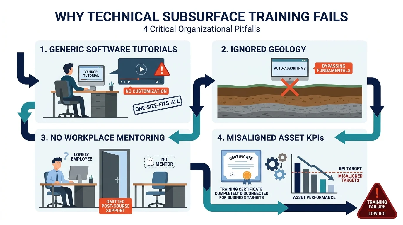
Many L&D initiatives fail to generate measurable operational improvements because decision-makers fall into predictable procurement and implementation traps.
Misconception 1: Vendor Software Training Equals Geological Interpretation Mastery
Service companies routinely offer free or low-cost software training focused on button-clicking mechanics. While staff learn how to navigate menus and generate tadpole plots, they do not learn how to distinguish a healed tectonic fracture from a drilling-induced artifact. Software proficiency without underlying geological and tool-physics competence produces high-confidence errors that corrupt downstream reservoir models.
Misconception 2: Automated Machine Learning Algorithms Eliminate Human Expertise
A widespread misconception among non-technical managers is that artificial intelligence and automated dip-picking tools eliminate the need for trained interpreters. Automated algorithms routinely misclassify borehole washouts, pad lift-off, and conductive mud streaks as natural geological dips. Human specialists must establish accurate training labels, audit algorithmic outputs, and apply regional geological context that software cannot replicate.
Misconception 3: One-Off Workshops Create Permanent Organisational Capability
Sending three geologists to a standalone public seminar rarely alters departmental performance. Without standardised corporate interpretation templates, peer-review checklists, and 60-day post-training asset integration projects, knowledge decay erodes 80% of newly acquired skills within one quarter. Sustainable capability requires cohort-based training paired with mandatory internal quality assurance workflows.
Misconception 4: Borehole Image Interpretation Is Solely a Petrophysicist's Responsibility
Treating image logs as isolated petrophysical deliverables prevents geological and engineering teams from capturing full data value. When petrophysicists work in isolation from structural geologists, sedimentologists, and drilling engineers, critical insights regarding sedimentary structures and stress orientations remain trapped in unshared reports. Effective corporate training brings cross-disciplinary teams together in shared workshops so every role understands how image data informs their specific operational decisions.
Frequently Asked Questions
What is oil & gas borehole imaging used for in subsurface evaluation?
Oil & gas borehole imaging converts high-resolution electrical and acoustic wellbore measurements into detailed structural, stratigraphic, and geomechanical models of subsurface formations. At the Institute For Oil & Gas Training, specialists learn to use these datasets for bedding interpretation, fracture analysis, and paleocurrent mapping to optimise well placement and reduce physical coring costs.
How does borehole image interpretation improve reservoir characterisation?
Borehole image interpretation resolves thin-bed laminations down to 5 millimetres, allowing subsurface teams to calculate accurate net-to-gross pay in complex clastic and carbonate reservoirs. By combining sedimentary structures with fracture density logs, geoscientists build higher-resolution static reservoir models that reduce drilling uncertainty and improve hydrocarbon recovery rates.
What is the difference between electrical and acoustic borehole imaging tools?
Electrical imaging tools measure micro-resistivity variations around the wellbore wall using button electrodes, making them ideal for resolving fine sedimentary structures in conductive, water-based mud systems. Acoustic imaging tools emit ultrasonic pulses to measure reflection amplitude and transit time, providing full 360-degree wellbore coverage for borehole breakout and fracture analysis in both water-based and oil-based muds.
Who needs corporate training in oil & gas borehole imaging?
Corporate training in oil & gas borehole imaging is designed for petrophysicists, structural geologists, sedimentologists, reservoir engineers, and drilling engineers involved in field exploration and development. Programs delivered by the Institute For Oil & Gas Training equip cross-disciplinary asset teams with standardised quality control and workstation interpretation workflows to minimise non-productive rig time.
Can borehole image logs replace physical core acquisition in exploration wells?
High-resolution borehole image logs calibrated with targeted sidewall cores replace expensive whole-core retrieval across up to 50% of development intervals while providing continuous, oriented geological data. Trained interpreters use these logs to determine structural dip, stress orientations, and depositional facies without incurring the rig downtime and laboratory delays associated with conventional coring.
Related training courses
Acoustic Borehole Imaging Technologies Training Course
- Specialisation
- Oil & Gas Borehole Imaging
- Duration
- 5 days · 15 CPD hours
Borehole Image Interpretation for Paleocurrent Analysis Training Course
- Specialisation
- Oil & Gas Borehole Imaging
- Duration
- 5 days · 15 CPD hours
Borehole Image Applications in Clastic and Carbonate Reservoirs Training Course
- Specialisation
- Oil & Gas Borehole Imaging
- Duration
- 5 days · 15 CPD hours
More articles
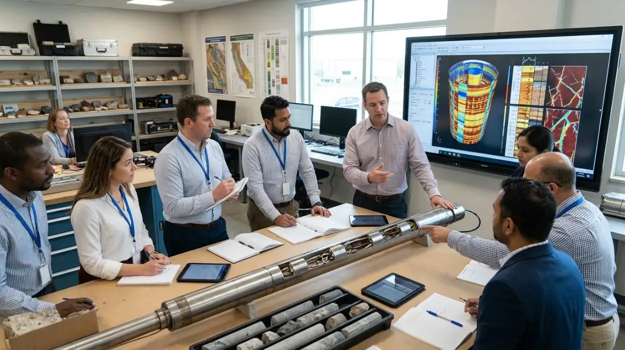
Electrical Borehole Imaging Technologies Training by Institute For Oil & Gas Training
Discover the curriculum, learning outcomes, and enrollment process for the Electrical Borehole Imaging Technologies Training Course.
Read article →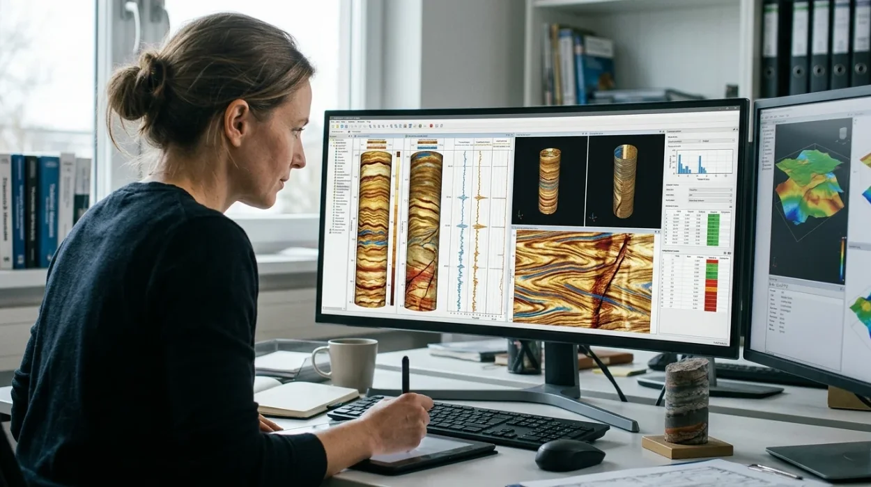
How to Evaluate Electrical Borehole Imaging Technologies and Their Applications in Formation Analysis
Master how to evaluate electrical borehole imaging technologies formation microimagers and resistivity logging tools for advanced subsurface analysis.
Read article →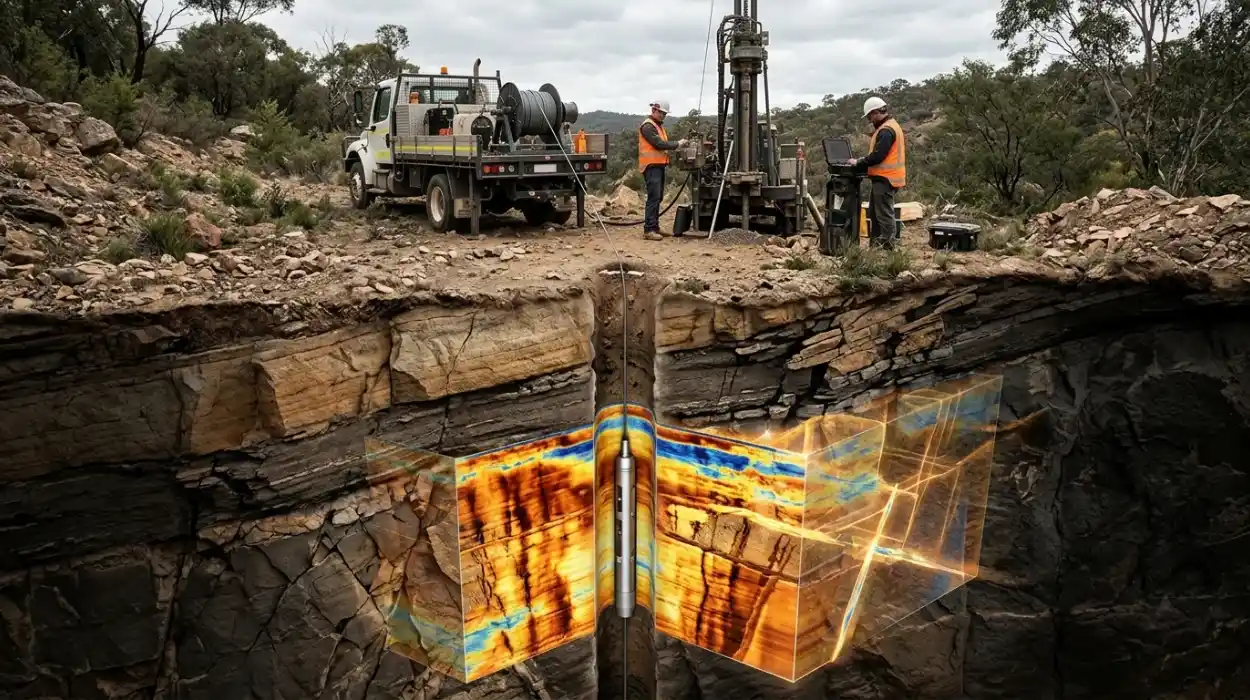
How Electrical Borehole Imaging Improves Subsurface Geological Understanding
Learn how electrical borehole imaging improves subsurface geological understanding and workforce competency through structured corporate technical training.
Read article →